
The death of the conventional gearbox wasn’t a murder – it was a mercy killing. The advent of the modern electric vehicle has allowed automakers to shed what is likely the most mechanically complex, costly, and now unnecessary part of a car. Torque converter? Don’t need it. Valve body? That’s black magic. Synchros? For what? 10 speeds? Sounds expensive.
A lot has been written about the slow death of row-your-own gear manual transmissions. I, too, mourn their eventual extinction. But if it’s any consolation, in an electrified future the same fate awaits the traditional slushbox automatic — and eventually, most gearboxes with more than a single fixed gear ratio. This time, though, it’s not millennials to blame for not knowing how to use three pedals. This time it’s the electric motor doing what it does best: ruthless efficiency.
Most enthusiasts know that electric motors (or electric machines, as they are often referred to in engineering circles) produce a lot of torque at low speeds. This is true, of course, but I think the understanding often ends there. What does the torque and power curve of the motor look like, and why? What tricks might automakers do to stretch the limits of a single speed reduction? And when might a multi-gear transmission still be advantageous in an electrified future?
My goal with this article, and perhaps future series, is to demystify some of the quirks of EVs. The average car nerd knows the four strokes of the internal combustion auto cycle by heart: suck, squeeze, bang, and blow. But I suspect that the workings of Maxwell’s equations, which govern what we know about electromagnetism and how EVs move, are more of a mystery.
EVs are often dismissed as soulless appliances, but I don’t think that’s fair. Turning electrons into motion is a choreographed act — a symphony of transistors pulsing current into tightly wound copper coils, conjuring magnetic fields through thin air that tug a chunk of steel and magnets into instant motion. It’s anything but lifeless. Maybe, with a little more appreciation for this, the loss of our right to row our own gears will sting a little less.
[Editor’s Note: Everybody welcome Zero Entropy! He is an auto industry enginerd who is going to impart some of his technical wisdom in the form of regular technical deep-dives! If you have any EV-related topics you’d like him to tackle, please let us know in the comments! -DT].
Understanding the Torque-Speed Curve 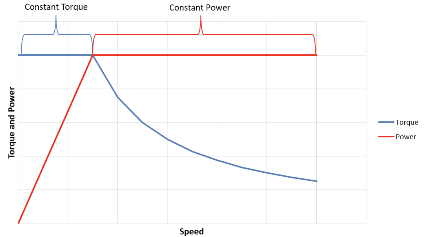
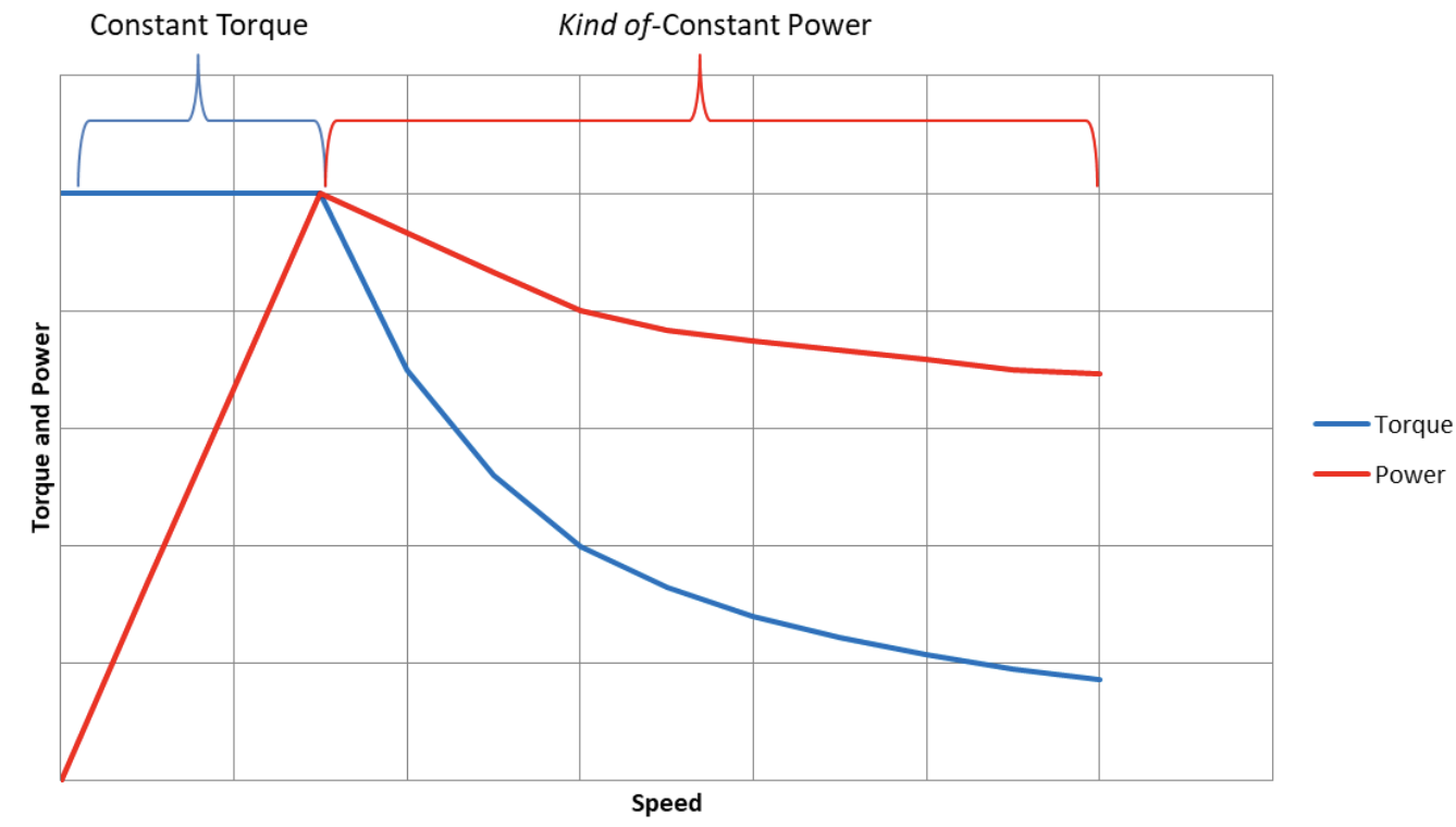
Appreciation for the electric motor should start with an understanding of the torque-speed curve. Most any type of motor found in an EV, be it induction, permanent magnet, wound field, or other will have a similar-shaped torque curve for the same fundamental reasons. Let’s dive into how that curve looks and why it behaves that way. We will use an interior permanent magnet motor as an example because it is the most common type of machine used in modern EVs and hybrids. The torque-speed curve can be divided into two sections: constant torque and constant power.
Constant Torque
If you’ve ever watched some of the viral EV acceleration videos, the ones with an unsuspecting grandma suddenly pinned back in her seat screaming, you know that the main performance aspect EVs excel at is making torque from a dig. It’s true that unlike the combustion engine, an electric machine can make all its rated torque from a stall.
At low to medium speeds, the torque is limited by the current flowing into the motor. The three-phase inverter (the power electronics box that feeds the motor) carefully controls the magnitude and phase of the sinusoidal currents flowing into each motor winding. Think of it like ignition or valve timing in an ICE — the current has to flow at exactly the right moment as the rotor spins.
As you might imagine, more current does equal more torque, but it comes with the same tradeoff every powertrain faces: heat. The inverter, cables, and windings all have some current limit, above which, bad things will happen and happen quickly. This heat does not go up proportionally with torque. The heat generated by a simple electrical resistor is defined by I^2*R (“I” being current, and “R” being the electrical resistance of said component). The squared term is the key here.
But what if we had really good cooling, you ask? Can we crank that Nissan Leaf to 11?! Well, sorry to burst your bubble, but even then, the motor hits an eventual plateau. The steel in the motor is only capable of so much magnetic flux density. When this “saturation” is reached, more current has dramatically diminishing returns. You end up making a heck of a lot more heat and not much more torque.
You might think that automakers, filled with warranty-obsessed bean counters, spec in a lot of safety margin into the peak current and torque limits of the powertrain. In actuality, the motor is usually designed fairly close to saturation levels. Those same bean counters want to get the most out of every bit of steel and copper they paid for. Careful monitoring prevents overheating. Sorry, tuners, there is not a lot of margin to boost your EV project here. EVs might be described by some as appliances, but they are not toasters.
In summary, the “constant torque” part of the torque-speed curve is limited by the current, thermal, and magnetic saturation limits of the motor and inverter system. To increase it costs real dollars: the motor gets larger, copper gets thicker, and cooling capacity increases. But overall performance is more than just low speed twist, what about high speed? To what speed can the system produce this torque, and why does it taper off? In the next sectio,n we will discuss the second part of the torque-speed curve.
Constant Power
Remember how I mentioned that the motor is often referred to as a “machine” in engineering circles? It’s a nod to the fact that the device can act as a generator, too. Understanding this is key to the second part of the torque-speed curve: the constant power region.
As the rotor spins, its magnets generate a voltage in the windings—thanks to Faraday’s law—that pushes back against the inverter’s voltage. We call this voltage back electromotive force or back EMF. It’s like trying to push water through a pump that is spinning the other way. The faster the pump spins, the higher the pressure opposing you is. In this case, the faster the motor spins, the higher this voltage gets. Eventually, the motor spins so fast that the back EMF equals the maximum voltage the inverter can apply (effectively the battery voltage in an EV).
When this speed is reached, the inverter can no longer push current into the motor. We are no longer limited by a maximum current, but rather limited by the voltage available from the battery and inverter at this speed.
The motor has hit a wall.
So how do we go faster? This is through some of the magic of modern controls in the inverter. This transition is referred to as the “Corner Point” on the torque-speed curve.
Beyond the Corner Point, the inverter is doing something called field weakening. Those permanent magnets spinning around in the rotor are producing magnetic flux, which is generating the back EMF that is in our way. To go faster, we need to reduce that flux and reduce the back EMF.
The inverter adjusts the phase (angle or timing of a camshaft lobe if you are thinking like an ICE) of the current so that it actually opposes the magnetic flux of the permanent magnets. Yes, we are using current to make the motor’s field weaker! We’re literally zapping the motor to make its magnets less magnetic. The result of this is lower back EMF, which allows faster speeds, but comes at the consequence of reduced torque.
This is why the torque speed curve looks the way it does.
The inverter can continue to field-weaken to faster and faster speeds. The torque will continue to drop. Power is torque times speed – so as torque falls and RPM climbs, the math works out neatly. The result is a broad, flat plateau of power delivery that feels like endless pull.
Electric motors have redlines too, based on mechanical limitations. The rotor will eventually fly apart at high enough speed from centrifugal forces! But their simplicity and compact design mean they can spin very fast relative to typical ICE found in everyday cars. Modern high-performance EVs are approaching 20,000 RPM. Even the Honda AP1 S2000 tachometer won’t suffice here.
This torque-speed story is why most EVs get away with a single gear. Between stump-pulling torque at zero RPM and that long, flat stretch of constant power to super high speed, there’s simply no need to shift. At any given speed the motor is capable of maximum torque OR maximum power. Shifting gears won’t change that.
Designing for Peak Performance
So is it that simple? There will never be a need for more than one gear?
Not so fast. Multispeed gear boxes won’t be totally dead in an electrified future, but I do think their application will be limited to special applications. Let’s dig into where there still might be life left.
First, we need to go back to high school physics to prove something that may be obvious to some of you: That horsepower is the ticket to quick acceleration. I promise you this won’t hurt that much. Just rearranging two equations to prove the point. First, Newton’s second law. Force is the product of mass and acceleration:
 Secondly, the definition of power is force times velocity:
If we do a little substitution, we get the following:
In a nutshell, acceleration is equal to power divided by mass times vehicle velocity. Put another way: for some given speed, the acceleration is maximized when the power is maximized. That wasn’t too bad, right?
Now let’s take that back to our torque-speed curve. This means that once we have gotten to a speed where the motor is in the constant power phase, the gear ratio no longer matters. Shifting gears won’t make it accelerate any quicker since the power is already maximized and constant!
At low speeds, however, gearing still matters. A lower gear (higher reduction) multiplies torque and lets the motor spin faster for a given road speed. Put the same as above, this means greater power is being produced for a given speed, and acceleration is greater.
So the gearing choice only really matters before you hit the Corner Point of the motor performance. In most commercial EVs, this usually happens around 30 to 40 MPH. After that, it’s all peak power.
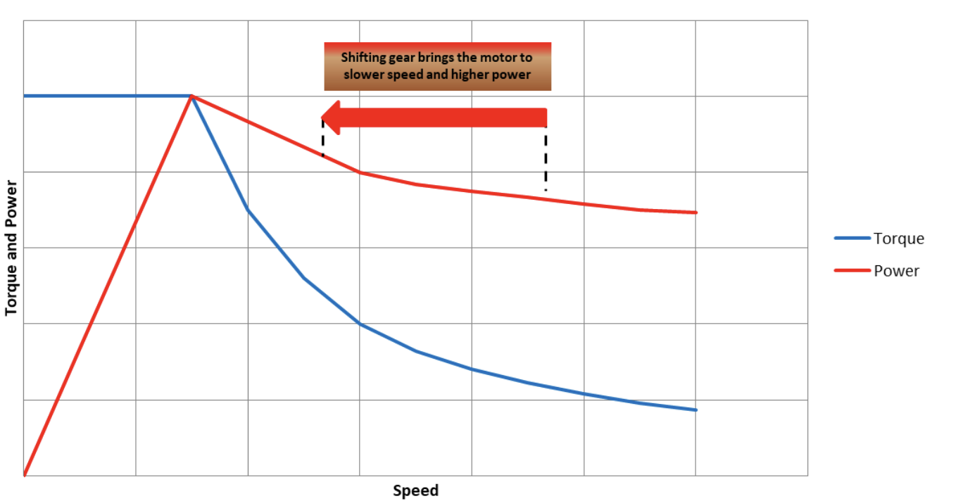
But here’s the rub: the constant power phase of the torque speed curve isn’t actually so constant in the real world. I lied earlier. Like so many things in life, the reality isn’t the same as the idealized version on paper. Constant power isn’t usually constant.
The degree of drop off varies from motor to motor, but a more typical real-world torque speed curve may look something like this:
For most EVs, their power actually tapers off at higher speeds. This is due to something called power factor and imaginary power. Despite the name, it’s not make-believe. It’s a real phenomenon that has to do with inductance and reactive current. If you want to learn more about imaginary power and other wizardry, you’ll have to sign up for my advanced course. For now, you will just have to take my word on it.
If you’ve watched any of the viral YouTube videos of EVs drag racing some muscle car, you may observe a familiar pattern: The EV jumps out to a quick lead, but then as power tapers off, it gets slowly reeled in by the snarling muscle car. Who wins depends on how long the race is.

This is where a multi-speed gearbox can earn its keep. Shifting puts the motor back toward its sweet spot near that Corner Point where it makes peak power. This is part of the same reason an ICE car needs to shift, but just a lot more subtle because the power in the EV curve is still pretty high across the board compared to an ICE.
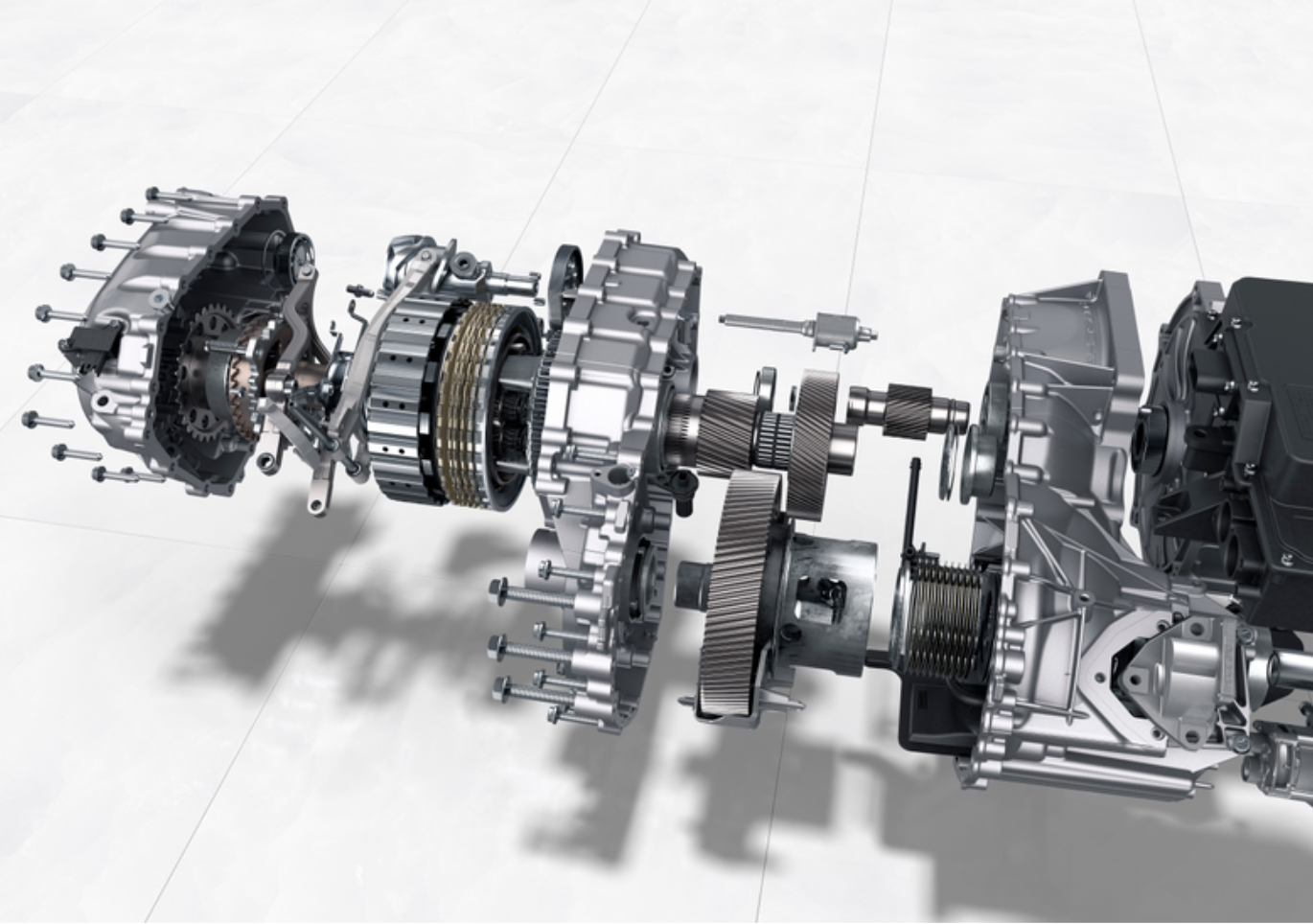
The best, and perhaps only example of this in a consumer vehicle, is the Porsche Taycan (and its Audi eTron GT sibling) with its two-speed gearbox. This is a high-performance vehicle, and the two-speed box helps keep the motor in a higher power operating condition, and it allows for some extremely high top speeds that may otherwise exceed the motor’s redline.
The other application I think we could see is some sort of multi-ratio gearbox in specialty off-road variants of vehicles.
We’ve established that EVs make tons of torque at zero or low speeds, so shouldn’t they be perfect for an off-road adventure through Moab? Yes, but the extreme cases still pose a challenge.
Imagine you are trekking over some boulders at an extremely steep angle. You’re inching over an obstacle, and the electric drive motors (presumably two or even four motors) are effectively twisting against gravity in a stall condition. They can make this torque, but heat can build quickly.
Using the motor to hold the car up an embankment is a lot like the first week you were learning to drive stick shift and you got caught in traffic on the steepest hill in town. Your poor clutch had to do the mediation between gravity on one side and an engine you are revving way too high on the other. I can still smell it.
Back to the EV; This is a case where a special crawl gear could be handy. Not because the motor isn’t capable of making the required wheel torque without it, but because it would run a lot cooler if it was geared down more. A greater reduction means the motor can be at a lower torque to make the same wheel torque. Lower torque means less current and less heat.
So in conclusion, while most EVs are perfectly happy with one ratio, there are still a few places — on racetracks and rock trails — where an extra gear or two can up the performance. Maybe the gearbox isn’t totally doomed after all.
A quick note about efficiency and economy: Yes, there is the small potential for a multi-speed gearbox to improve vehicle economy and put the motor in a more efficient operating condition, but any advantage typically isn’t worth the added cost and complexity of a gearbox like that, especially on an economy-focused EV. In general, the electric motor tends to be very efficient across the torque-speed range.
Cool Tricks Automakers Use Instead of Changing Gears
The single-speed transmission is adequate for most EVs as we’ve discussed, but it still has some disadvantages. Automakers have a few tricks up their sleeves to make up for it.
The first is to use different ratios for front and rear motors (in a dual motor AWD vehicle). The rear motor, for example, can be geared lower (greater reduction) to provide maximum acceleration off the line when the vehicle’s weight transfer is shifted most to the rear tires, giving them the most grip.
The front motor will be geared taller. As the vehicle gains speed and the rear motor crosses the Corner Point, its power will gradually drop off, but the front motor will be hitting its stride and is no longer grip limited at this speed. Overall power never fades.
The driver gets the benefit of two different ratios, each optimized for a different vehicle speed, all without shifting any gears!
But the most interesting trick might be what Kia is doing with the EV9. It has been reported that the EV9 has a motor that can switch the way the motor windings are configured on the fly.
Electric motors in EVs almost always have all three phases. Those three winding phases can be connected in two different ways: delta or wye. Illustrated below are the two configurations. The inverter will connect to the terminals A, B, and C and manage the rearrangement.

At low speeds, the motor is configured in wye mode, which generates a higher back EMF. This maximizes torque, but hits the Corner Point and is voltage-limited sooner. Switching to delta configuration lowers the back EMF at the terminals and allows higher speed before hitting its voltage limit. Changing between the two alters the torque-speed curve. It’s like having a two speed gearbox made from transistors, not gears. (See The Autopian’s deep-dive into Kia’s drive unit here).
It’s a reminder that while electric cars may have done away with overly complex mechanical gearboxes (engineering wonders in their own right), they haven’t killed ingenuity. Car people love complexity; carburetors, pushrods, turbochargers, and all the drama that comes with it. I think a lot of that love comes from seeing all these complex mechanical things in motion. With an EV, it’s a different dance that is more invisible, but one that I think is just as fascinating.
Top graphic images: BMW


More! MORE! Autopian FTW!!
I plan to do some more articles like this. If you have specific topics you’d be interested in, post it here!
Electric motors are very compact for their power output, no? So why not do exactly what performance cars have always done and just use a honking ass single motor with power that doesn’t drop off till say the sound barrier?
Good question! I have a few thoughts on this:
On the point of costs I argue if a manufacturer is charging high six or even seven figures for a performance EV they shouldn’t be skimping on motor(s). Or anything. really. The limits should be those imposed by the bleeding edges of the technologies involved, not by the accountants.
It’s my understanding that making bigger motors isn’t the main challenge, it’s getting everything else around the motor to keep up. I think that’s where your “bleedging edges of the technologies involved” come into the picture.
Some are still open questions, some are solutions that work in a lab yet to transition to the real world, and some solutions exist but challenging to do at size and weight of a passenger vehicle. (See Hyundai’s wye-delta switchover.)
Downstream example: tires that don’t instantly go up in smoke.
Upstream example: power control electronics and battery that can deliver enough electricity without themselves going up in smoke.
Chemical reactions inside a battery can only go so fast before sacrificing longevity. One workaround is to have literal tons of batteries and draw from them in parallel, but that makes other problems worse. (See Hummer EV)
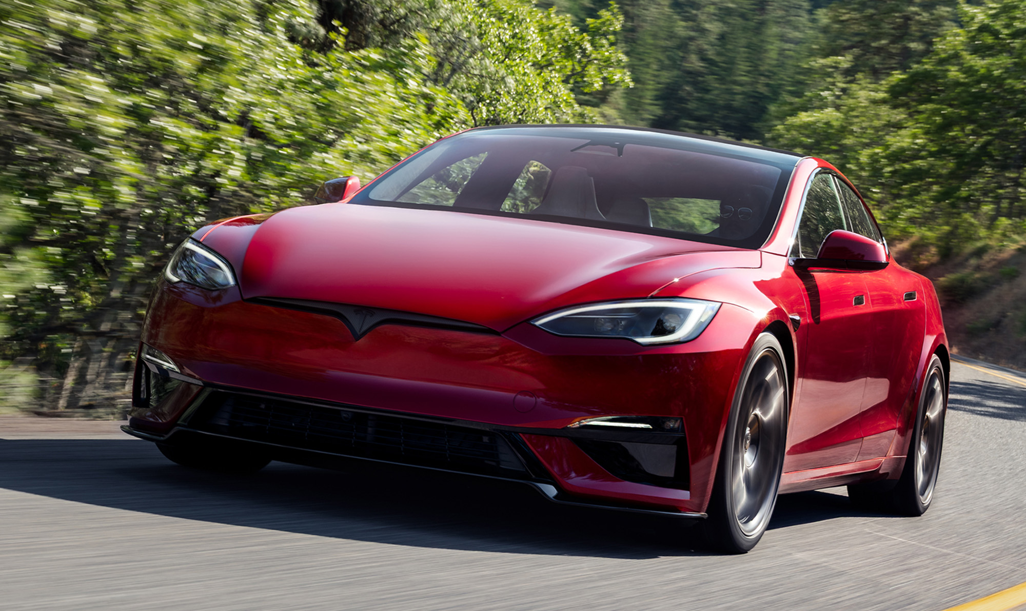
Tesla has a 4800 lb sedan that can go 200 mph and from 0-60 in under two seconds with a claimed range of 410 miles and a fast charge time of 15 minutes. That’s amazing and way more performance than anyone needs. Clearly everything else in the car is up to the challenge but the car uses three motors to do so. So reducing that arrangement to one motor to rule them all may be the next frontier*.
* A frontier I’m happy to forego in lieu of finally building that damn $20k car!
Really interesting article, and stupendous writing. Well done!
Thanks, Matty
“Car people love complexity; carburetors, pushrods, turbochargers, and all the drama that comes with it”
It’s all fun and games till drama turns an asset into an albatross.
I only like the drama when i am not depending on it to get me home.
THAT…
…was a fascinating journey. And the bit about the Kia reconfiguring itself on the fly, I never even suspected. It’s genius.
It’s actually an old technique used in other industries, but for the first time used in an automotive application. I get the impression Kia let their engineers have a lot of liberty in doing cool stuff like this.
Great writeup! Welcome to the Autopian.
PS: Although I need to make time this weekend to read it again, something about the power and torque curve becoming strangely unfamiliar when applied to an EV
Thank you!
Isn’t some of why the current crop of BEVs tend to be bonkers acceleration beasts based on the motor size and current capacity needed for effective regenerative braking and and large battery capacity required for a marketable range?
The torque-speed curve shown in the article is only in one quadrant. The regen capability is symmetric of this (but if we are being exact, the motor can actually make slightly more regen torque than it can in motoring).
So effectively, the motor is capable of slowing the vehicle down at about the same rate as it can accelerate it.
A big battery compliments the powerful motor. Afterall, if the battery can’t supply that power, it is the bottleneck in the system.
What matters isn’t horsepower (or torque) at the motor. It’s torque at the wheel – which is horsepower times gear ratio. Given the above, and the constant power of the electric motor, wouldn’t the lowest possible gear ratio (highest gear reduction) be the highest performance?
If that is true, it would follow that with the same motor and drive voltage an ev geared for a top speed of 80mph would be faster than one with a top speed of 120mph (everywhere below 80mph). Am I understanding the physics correctly?
Good analysis. You are correct. The greatest reduction would get the motor to peak power the “soonest”. So at least the initial acceleration would be the greater. If the power stays truly constant from then out, the gearing no longer matters.
However, this means the motor is spinning faster for any given vehicle speed. Beyond the top speed limit, there are some other small things to consider: durability, friction and so called “windage” losses and even NVH (noise, vibration and harshness).
My question is in the constant power region only. I get your point – that if I add gear reduction in the constant power region, the motor speed increases. The increased speed results in increased back EMF. The controller has a maximum voltage it is already supplying, so to overcome that additional back EMF there is less voltage /EMF that reaches the magnet and is available to do work – and the net result is the same torque at the wheel regardless of gear ratio (in the constant power region).
However, I cant reconcile that with my ICE understanding that more gearing always makes the car accelerate faster. Its like I’m trying to reconcile relativity with quantum mechanics – I need a unified theory…
On another topic, I’m an ME that has to select motors. For backlash / control reasons we typically use direct drive – so large motors with large Km are used. If we didn’t need direct drive, a small motor spinning fast with a gear reduction intuitively seems more efficient. For my direct drive application, a larger Km motor is always more power efficient. If Km were the only thing that mattered for efficiency, I’d assume all EVs would have the largest motor they could package for the increased efficiency. How does Km relate to the efficiency of an EV?
The theory is still unified. Keep in mind the CT/CP curve shown is always theoretical. You can’t climb too far to the right without certain electrical parasitic effects potentially making your inverter current control loop unstable (causing explosions) or simply making the real current inside the motor too high.
So, you can’t “infinitely speed up the motor and then infinitely gear down for torque/acceleration”. You can out to a certain point, and then plenty of other factors weigh you down.
You can analyze vehicle acceleration in two ways. First just using F=MA and calculate the wheel torque using the gear reduction at any given speed. Easy.
But by including the reduction and looking at the motor torque at that speed you are effectively defining the power. Since power is force*velocity.
So that is the second way, just look at power. It’s really the same thing.
In my example, I think it was easier to make my point just thinking in terms of power at a given vehicle speed, but it is equally valid to calculate wheel torque at that speed too.
_______________
I did a little searching to make sure I was on the same page about “Km”. That’s a constant not used in my industry. But I think I understand, it’s just the ratio of torque you get per input power at stall, right?
For the car application this gets complicated. Indeed the largest motor with the most copper will have lower stator resistance. That means current and high torque can be made with lower I^2R losses.
However, an EV spends very little of its time at peak torque. It actually spends most of its time at very low torques. Like a few % of peak. It does not take much to push the car at a constant speed! This also happens to be an area where the efficiency is relatively low. Slightly higher load actually increases efficiency. Thus, massively oversizing the motor has some efficiency hit at these operating conditions.
This is part of the reason why dual motor EVs get worse range and economy than single motor variants. Besides the added friction, if both motors are active each motor is now producing less torque than if they were alone and loaded more. This puts them in a worse operating condition for efficiency.
This is a subtle effect, but something to consider when squeezing every mile out!
So why did my drill start smoking the other day? (Joking, it’s over 20 years old and it’s been used hard.)
Good article. The details are way over my head, but I think I get the gist.
I do object to being called a “bean counter”. We accountants just tell management what things cost and they determine how best to meet their budgetary restrictions. It’s not our fault they decide not to spend $100K to make a $50K vehicle. 🙂
We have to pay the bills at the end of the day somehow!
Great article! Looking forward to more of stuff like this.
Thank you.
My friend is connecting a Nissan Leaf power unit to the transmission on his Scout 800, and not just bypassing it. There are several reasons, but this article does a better job of explaining some of the advantages than I’ve been able to (other than just saying it’s just easier to keep the stock transmission/axle setup).
Many EV conversions still use conventional transmission, I have observed. As you say, part of that is for the reasons i describe, but also i suspect due to necessity of hooking things up.
For an off-road vehicle that is likely to be spending much longer periods of time with minimal motor speed this makes more sense, since both lubrication and motor cooling use the gearbox and motor oil, and are dependent on the motor spinning faster than a certain low threshold to pump that oil effectively. If you’re regularly operating below that at high torque, you risk motor or gear reduction bearing damage, plus the thermal issues the author mentioned at high current are compounded when you don’t have as much cooling capacity since the motor may not be spinning fast enough to pump enough oil (and of course the vehicle angle off-roading is far less predictable, so oil return to pump pick ups is more variable)
Wow. Thanks for the fantastic content. It’s so nice to have the old info dragged out of the attic and tied into new applications. What is the p.f. in a modern permanent magnet machine? I’m very much looking forward to more like this.
Thanks! PF values I don’t typically pay attention to in my work, but in the constant torque region it will be a constant value well above 0.9.
As the machine goes faster in field weakening it will drop. If you spin fast enough (likely beyond the mechanical limits) PF eventually becomes 0 for the typical non idealized IPM.
So, are you telling me the Taycan found a way to repurpose the Powerglide?
a side note, a superscript 2/“squared symbol” is defined in unicode: ²
super cool to see some of this nerdy engineering content but if it’s going to be common this website should really support LaTeX or something so formulas aren’t regular text in bold and 4x bigger
wordpress supports it out of the box…
Drifting into hybrid world, but I think this helps explain what happens when I figured out how to gain some acceleration driving my Gen 2 Prius. When I want some acceleration to pass or hit a curve, I back off from gas-based acceleration just a bit, but not enough to lose speed, then hit the pedal to accelerate. This would reduce the electric motor speed to bring it down to a better place to allow better acceleration. Anyway that is what it felt like.
I suspect that is just a quirk of how the controls work. Perhaps that lift off and punch feels like a kick in the pants.
The Prius powersplit transmission can change it’s gearing.
If I just hit the pedal, it would not give the same acceleration as backing off just a bit, and then hitting the pedal this the quest for a technical explanation.
I have a question about these motors. What does the drive frequency have to be to spin these motors in say a Mach E at 100 mph, knowing that there’s a reduction great in there for torque?
Given that these are really big inductors, and the frequency is pretty high, the voltage is pretty high (for semiconductors) and the current is high, are there any unusual difficulties in the motor controllers?
Separate question. Knowing that railroad locomotives generate electricity which drives traction motors, and they are relatively efficient, why aren’t we seeing ice cars that ditch the transmission and do the same thing?
If you mean the switching frequency of the inverter, it often varies with speed and torque. Could be as low as a few kHz and over 15kHz with silicon carbide (SiC) mosfets.
Concerning your second question, what you are describing is the “series PHEV”. It is actually gaining traction in the form of so called “extended range electric vehicles” or EREVs.
This is a mechanically simple design, but consider that each time you have an energy conversion, there are losses. So sometimes it can be better to have the engine directly drive the wheels as other hybrid systems allow. Its a trade off like everything!
Thanks for the awesome reply!
There’s two “drive frequencies” you might be thinking of. One is intrinsically how fast the inverter is scientifically touching the battery to the motor, called switching frequency or chopping frequency, and yeah it’s usually 15kHz and up these days. The faster this frequency, the quicker and more accurately you can control the current in the motor in essence.
The other “drive frequency” is called commutation frequency, and is how fast the rotating magnetic field inside the motor is turning, caused by the inverter scientifically touching the battery to the motor. That’s dictated by the way the motor is built internally and the vehicle’s gear ratio.
Your average EV has a gear ratio of about 10:1, so you can imagine a wheel spinning at 1,000 RPM making the motor spin at 10,000 RPM. The simplest possible toy motor has a north and south pole on the magnet – this is called a 1-pole-pair motor.
More commonly, traction motors are 2-4 pole-pairs, or even more (think 3 or 4 bar magnets glued together like an asterisk, each one facing the opposite direction as the last, in principle) to make them smoother in operation. This implies the rotating magnetic field has to spin 2-4 times (called electrical speed, eRPM, and a few other names) as fast as real life (mechanical speed of the shaft).
Let’s say our traction motor has 4 pole pairs. That imples the eRPM is 40,000 compared to the mechanical speed of 10,000 RPM. Each revolution of the magnetic field will therefore take only 15 milliseconds. Each revolution of the actual motor as you look at the shaft takes 60 milliseconds. By comparison, each switching frequency cycle of the inverter at 15kHz is 0.00006 seconds (0.06 milliseconds). Many switching cycles take place in one commutation cycle, allowing you to carefully control the current flow in the motor.
The difficulties that this all presents at high power is pretty much just making the inverter bigger than it needs to be and sitting around waiting for semiconductor technology to improve. The faster you switch, the more losses (heat) in the inverter just by virtue of herding more electronics in and out of something per second, and you can also switch a transistor so fast it’s just half-assedly on and half-assedly off, which greatly causes losses and explosions. The semiconductors of today are far, far better than even in 2010 and just completely a different world from the 80s-90s.
(Interestingly enough the roughly 33″ diameter tire of a Mach E spinning at 1,000 RPM is around 98mph… so, uhh, there you go, the drive frequency is approximately 660Hz)
Ha! Thanks!
OMG I’m learning so much the top of my head is hot! Thank you! I didn’t realize at that power level and that inductance that tens of KHz was plausible!
Funny enough, “more inductance” to a degree makes controlling the current easier. It is pretty easy to think of it as a flywheel.
There exist a few motor designs with very low inductance that for the longest time in the 2000s and 2010s would fuck up inverters not specifically built or tuned to accommodate them. Back then, the power semiconductors simply couldn’t switch fast enough, the low inductance caused currents in the windings to fluctuate very quickly, and your control loop turns upside down and everything explodes.
sauce: mine exploded
PHEV’s can operate like a locomotive. The ICE engine is connected to a motor-generator to create electricity for the traction motor
I didn’t realize!
This is awesome and the best explanation I’ve ever seen on all this stuff. Answered a lot of questions I’ve had for years! I think my heart will always belong to ice but with more detailed explanations of EVs like this and what makes them work/different manufacturers unique I can learn to appreciate and enjoy more aspects of the necessary EV world.
Thank you! Something something we fear what we don’t understand.
Exactly. I’ve spent years learning about how ice work, and despite not being an engineer I can appreciate the differences in engines. But I’ve had no training and few articles that have helped me learn the little details about EVs (I’m sure most auto journalists are in a similar place as me, they just don’t know anything about EV details either). This is an excellent start to deeper understanding, thank you!
Truth. ☆☆☆☆☆
Sorry electric motor replacement of expensive manual transmission parts doesn’t convince me when the Electric vehicle is twice as expensive as the ICE car. Insane it is like the government every time they say they are saving us money taxes go up. Don’t try to sell that snake oil around here.
Hear, hear.
Old man shakes fist at clouds. News at 11.
Come on. China is selling a full EV for 20 grand. Pushing EVs is about having a car industry in the 21st century by getting to economies of scale on the batteries.
I’ve been thinking about something like this should happen for a while now.
Why waste time with increasingly expensive multispeed automatics when you can just pair the given engine to a hybrid transmission.
In my world view, what should happen is Toyota or Chevy Volt style “eCVT” hybrid tech replaces all those 6+ speed automatics as well as regular CVTs.
Then as an option, offer a bigger battery and plug-in capability.
And above that, BEVs on dedicated BEV platforms rule the luxury and near-luxury segments. And hypercars would also use BEV tech, with or without an ICE to extend range
And manual transmissions make a comeback in budget and sporty/sports cars.
This last point is pure fantasy.
The old Fusion hybrid and PHEV version of that come to mind from what you describe.
Incidentally I have a 2017 Ford C-Max which has the same hybrid and PHEV powertrain as the Fusion.
OK, Ok, hear me out. A motor attached to another motor. Revolutions squared. Top speed times top speed. Axial motor parallel to another in-line. Checkmate flatworlders.
What about efficiency? These motors are really inefficient in the constant torque zone. Gearing can be used to keep the motor in high rpm high efficiency.
Sure right now going from 50 mpg to 100+ mpge is amazing and seems like we will never need more…
Peak efficiency does tend to happen past the corner point, but operation at speeds below that is still very efficient relatively speaking.
Also, at low speeds the output power is low since it doesn’t take much to push a car at 20 mph. As such, even if the efficiency is worse percentage wise, the absolute loss is small compared to high speed / high power operating condition – that is where we care more.
Every economy improvement you can make saves money for the automaker (less battery needed), but adding multiple gears is unlikely to pay for itself as the differences are fairly small.
You’re inevitably going to be doing an article about motor types at some point. My question is about the much hyped axial flux motor. I believe in the size/packaging and weight claims, but seemingly every article focuses on their potential use as in-wheel hub motors, which I am personally very skeptical of. Even if the motor could survive the extreme amount of shock and vibration (though aren’t super tight rotor-stator gap tolerances their biggest barrier to mass production?), I highly doubt that it’s a good idea to subject a gear reduction those conditions. Which brings the question, are axial-flux motors torquey enough to directly drive the wheels without a gear reduction while being small enough to fit inside the wheel rim?
Even if the answer is yes, I still don’t think they’re a good idea because of the huge amount of extra unsprung mass they’d add. The better solution if individual wheel drive is desired is to mount the motors on the sprung body like normal and send a shaft with a CV joint to the wheel like normal IMO; it also still allows for a gear reduction if needed.
I agree with your points and share the skepticism about mainstream in-wheel motors. Consider also that you need to route DC high voltage wires out there assuming the inverter is at the wheel, or three phase wires out there if the inverter is inboard of the suspension. That poses a challenge.
Axial flux benefits from being more torque and power dense, so I think it could make the needed torque. Perhaps if necessary it could have some sort of hub reduction even (like an ebike wheel motor!).
We have yet to see this on anything for the reasons you state. Also there is the fact that if you want to do in wheel motors, you need at least 2 of them per vehicle for left and right. I think the industry is going to move towards cheaper, economy focused EVs in the near future rather than the super performance $100k vehicles of the past few years. As such, for the time being I still suspect a single motor in the usual spot with two half shafts is cheaper than multiple in wheel motors even if they worked.
Having done some vehicle layouts for axial flux motors I’d say they have some annoying package constraints. The relatively large diameter to length ratio tends to favour epicyclic gearboxes, rather than a nice simple reduction gear.
Not a problem when used with a hydrid ICE/REEV as it’s the perfect shape for a pancake motor, but for a pure EV you end up with something tall and thin to package on the centreline of the car.
I spent the few years doing package studies on every available EDU or motor we could find, to build a library of benchmark data. I don’t miss doing that at all.
Yes you have discovered the conundrum of the EV industry from approximately 1998 to 2014. Everybody and their grandma tried to make direct-drive axial flux wheel motors happen and everybody came to the same conclusion, that it sucks.
The torque wasn’t super the issue so much as the unsprung mass and difficulty of packaging everything else. This was less a problem in big industrial vehicles like buses (I recall one or two production european buses with hub motor drives).
When Lordstown tried to do this with the Endurance, I 1. wanted to believe badly and 2. knew it was over.
“EVs might be described by some as appliances, but they are not toasters” Maybe not, or maybe? Some EV’s still have a reputation for randomly burning when not expected, Just like Toasters.
I knew this would get some reaction. I teed this up for you!
All cars do that.
Yep, but like Pinto’s and S10’s once the rep gets stuck to you, it is easy joke fodder.
Thank you for this. Even if you might be A.I.
Yeah, same thoughts, at least on the AI side of it.
I am a real sentient being.
That’s just what an AI would say…
We are all in a simulation, so…
Only a simulation can have zero entropy. Q.E.D.
But simulated entropy is still entropy, right?
If you simulate no entropy, the simulation will still be subject to entropy. Unless it is also a entropyless simulation…
That’s also what an actual AI would be.
It made too much sense to be AI.
Are you like Data on Star Trek? He was deemed to be sentient too!
The measure of a man is one of my favorite TNG episodes. To be compared to him is an honor.
Yeah… definitely a great episode.
*eyeing you suspiciously*
Great article! In a different Munro & Associates teardown, they found that H/K motors used in the Ioniq 5 were bar-wound (4 bars IIRC) rather than wire-wound. This allows for a higher copper cross-section in each winding (and thus lower resistance in the I^2R equation), but at higher speeds the skin effect is worse due to the lower surface area. Do you think it’s worth it to use a 2-speed that lowers RPMs at highway speeds to avoid the skin effect allow for lower bar counts (3, 2, even 1)? Would reducing the bar count come with other advantages like making manufacturing cheaper?
Really in depth question! Thanks Needles Balloon!
In short, the loss associated with skin effect is going to be very small. Not enough to justify a complex and costly 2 speed gearbox.
What you are referring to is the “copper fill factor”. Square wires, called “Hairpin”, improve the fill factor a lot. The advantages there outweigh any small skin effect overall.
A good example of all the little tradeoffs that happen in the design process!
Very interesting! The Munro Live presenter made it sound like the skin effect losses were a significant factor at highway speeds, big enough that sticking with wire windings was a valid choice if you wanted to prioritize highway efficiency or use shorter gearing. If it is indeed insignificant, we could probably assume that all EVs going forward would try to have hairpin windings if possible, cost allowing.
Yes, most of the industry is going Hairpin from what I have seen.
This is one of those times when the designers have to try to optimize around the operating conditions of the car, and perhaps optimize around the EPA test cycle, which is NOT high speed.