
If you’ve been around this crazy automotive world as long as I have (my ample grey hairs prove this to be true), you will probably remember the early days of front-wheel drive cars. If you ever drove one of these cars, you will probably also remember a problem many of them had that caused them to steer all by themselves whenever you hit the gas pedal. It’s called “Torque Steer,” and it is something no FWD car is immune to, even today.
So, what is Torque Steer, how is it generated, and are there things suspension engineers can do to eliminate or at least mitigate it? Let’s dive in.
[Ed Note: Welcome back our resident suspension engineer, Huibert Mees. He took a bit of a break, because he deserves one after developing the Ford GT’s and Tesla Model S’s suspension. -DT].
A Little History
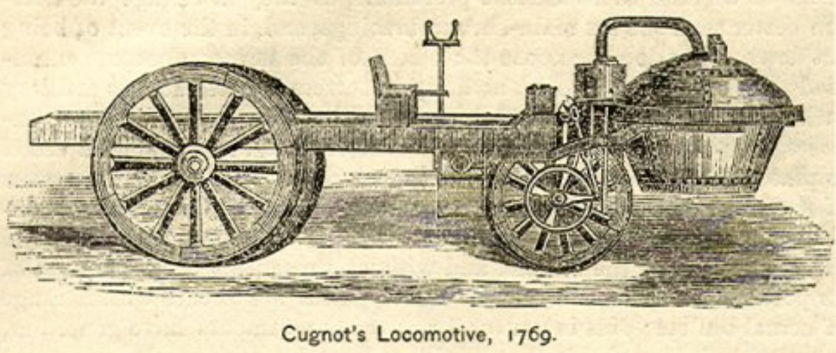
Front wheel drive cars have been around for a long time. You could say that it is the original drivetrain configuration since the very first self-powered vehicle, the gun tractor built by Nicholas Cugnot in 1769, used it.
Driving a single front wheel is one thing, but as automotive design settled on 4 wheels, the technical challenges of getting the drive torque to two wheels that also had to steer kept front wheel drive from becoming the norm that it is today. That’s not to say some didn’t try. Cord famously used it in 1929 for the L-29.
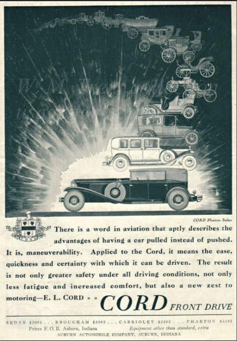
Unfortunately, the perception that the L-29’s top speed of 80 mph was a bit tame, as well as the looming depression that started right after the car was introduced, kept it from being a commercial success. It’s a shame, really, because these cars are stunning and much sought after today.
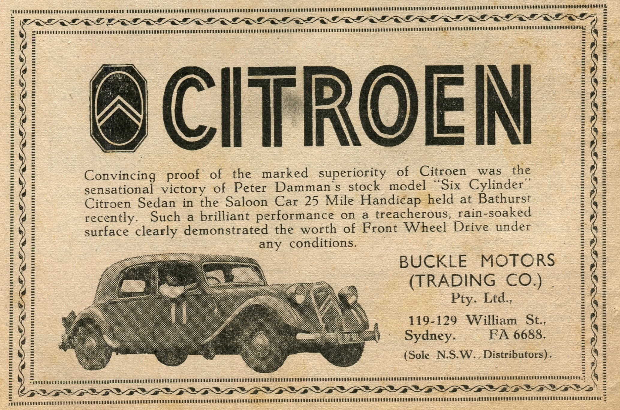
A few years later, Citroen would have a go at it with the Traction-Avant, which literally means “front drive.” This time, however, it proved to be a much bigger success, with production peaking at just under 20,000 cars in 1936. If you want to see one of these in action (and hear some gorgeous music), watch the film Diva.
After the success of the Traction Avant, Citroen would go on to use front wheel drive in most of its subsequent models. GM would also make a go of it in the mid 60’s with the chain-driven Oldsmobile Toronado and the Cadillac Eldorado, but these were relatively niche vehicles.
As far as the general automotive market goes, front wheel drive didn’t take off until the 70’s after the 1973 oil shock sent many customers looking for smaller, more efficient cars. Japanese manufacturers like Honda and Toyota had just the ticket: small front wheel drive cars. Since these cars were small, space was at a premium. Anything to get more interior room for passengers and cargo made them more appealing. Front wheel drive, with its lack of a large central tunnel to package a driveshaft made it ideal for these types of cars. Compare a Chevy Vega or a Ford Pinto with a Honda Civic or Accord from this era and you will see the advantages of the front wheel drive configuration on interior space.
Over time, front wheel drive became the norm for anything except high end luxury and sports cars and as it became more accepted, the demand for more powerful engines started to increase. These more powerful engines exposed a problem previously masked by the lack of power of the earlier cars: torque steer.
What is Torque Steer?
Torque steer is a phenomenon in which some aspect of the drivetrain design — or the road and driving conditions — cause the car to steer by itself, right or left, under hard acceleration. It can happen in either front wheel drive or rear wheel drive cars, but it is most prevalent with front wheel drive since the drive wheels are attached to the steering system.
So, how is torque steer generated and is there anything we can do in the design of the car to eliminate it?
Torque Steer Mechanisms
There are two basic ways in which torque steer can be generated: un-equal application of drive forces at the left and right wheels, and un-equal left and right halfshaft outer constant velocity (CV) joint angles.
Let’s talk about each of these starting with un-equal application of drive forces to the left and right wheels.
Un-Equal Drive Forces
As torque travels from the engine through the transmission, it passes through the differential and is split between the left and right halfshafts. In a standard “open” differential, the torque is split evenly between the left and right sides. The open differential design ensures that both halfshafts always get the same amount of torque, regardless of tire friction.
The torque travels down the halfshafts, through the wheel bearings attached to the knuckles and into the wheels and tires. The friction between the tires and the road converts the torque into a force, which propels the vehicle forward. As long as the friction levels between road and the left and right tires are similar, the forward force generated by this friction will be about the same left and right.
However, if the friction levels between the left and right tires are very different, such as when one tire is on ice or wet leaves, then the tractive capability of the tires will not be the same. Here is where the design of the suspension and the differential come into play.
If we look at a generic double wishbone suspension, we see that the axis the suspension steers around is defined by a line through the upper and lower ball joints.
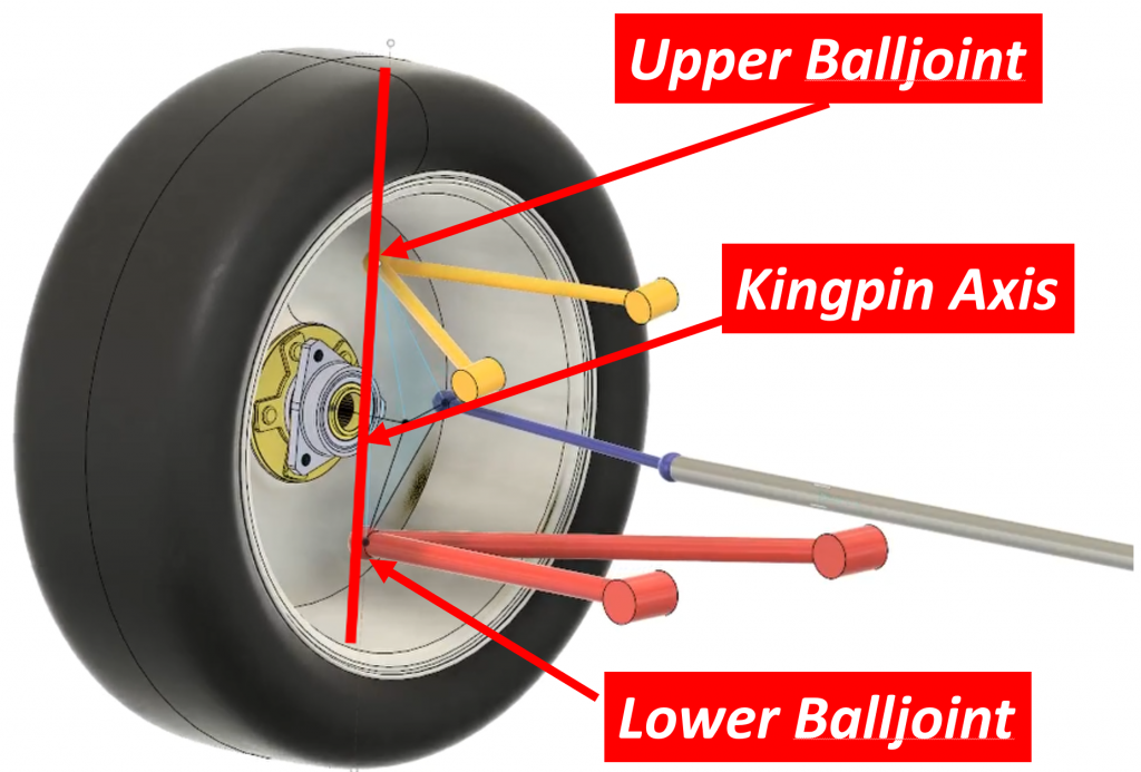
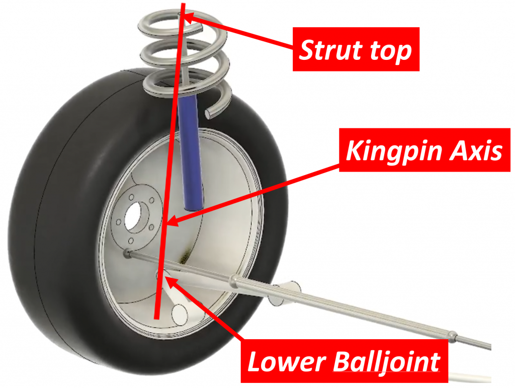
This axis is called the steer axis or kingpin axis. In a MacPherson strut it is defined by the lower balljoint and the top of the strut:
This axis functions like the hinge axis of a door. The door rotates about the hinge axis when you open and close is just like the wheel rotates about the kingpin axis when you steer it.
Now, let’s look at where the tractive force is applied. If we think of the vehicle as a whole, the force accelerating the car is generated between the tires and the road. This means the force pulling the car forward is located at the tire contact patch.

However, in order to understand torque steer, we need to look at it from the perspective of just the suspension, not the total vehicle. When we do that, we see that the torque traveling down the halfshafts passes through the knuckle via the bearing. As the torque passes through the bearing, the part of the bearing attached to the outer CV joint just spins while the outer housing of that bearing (a housing that is attached to the knuckle) sits there stationary. There is essentially no torque transfer between the halfshafts and the knuckle. There is, on the other hand, a force that happens between the bearing and the knuckle. As the wheel spins, thanks to the tire’s traction with the ground, it “pushes” the vehicle (and suspension) forward through that bearing, but since the bearing can only transfer a force to the knuckle, as far as the knuckle is concerned, this force happens at the center of the wheel.

It is critical to fully grasp this because the location of the drive force on the suspension is central to how the suspension, and the steering system, react to it.
Let’s go back to our suspension model to see what this all means, because as you can see here, it’s pretty intuitive — the car moves because the road is effectively “pushing” the car forward through the wheel, which is connected to the rest of the car via that bearing in the knuckle.
When we add an arrow representing the drive force to our model…

…we see that there is an offset between this arrow and the kingpin axis.

It’s a little hard to see since it’s a 3-dimensional problem, but this offset is called the “kingpin offset.”Suspension engineers spend a lot of time trying to get this distance down to a minimum, but as we’ll see later, there are limitations on how small it can get.
What the kingpin offset means is that the drive force is pushing on the suspension not directly on the steering axis, but at some distance away from it. Imagine pushing on a door right at the hinge axis. The door wouldn’t move. If, on the other hand, you push on the door some distance away from the hinges, the door will move, and the farther away from the hinge axis you push, the easier it is to make the door move.
The same goes for a suspension. The larger the kingpin offset, the more the drive forces try to make the suspension steer. But the suspension can’t steer by itself because it is connected to the steering system through the tie rods.
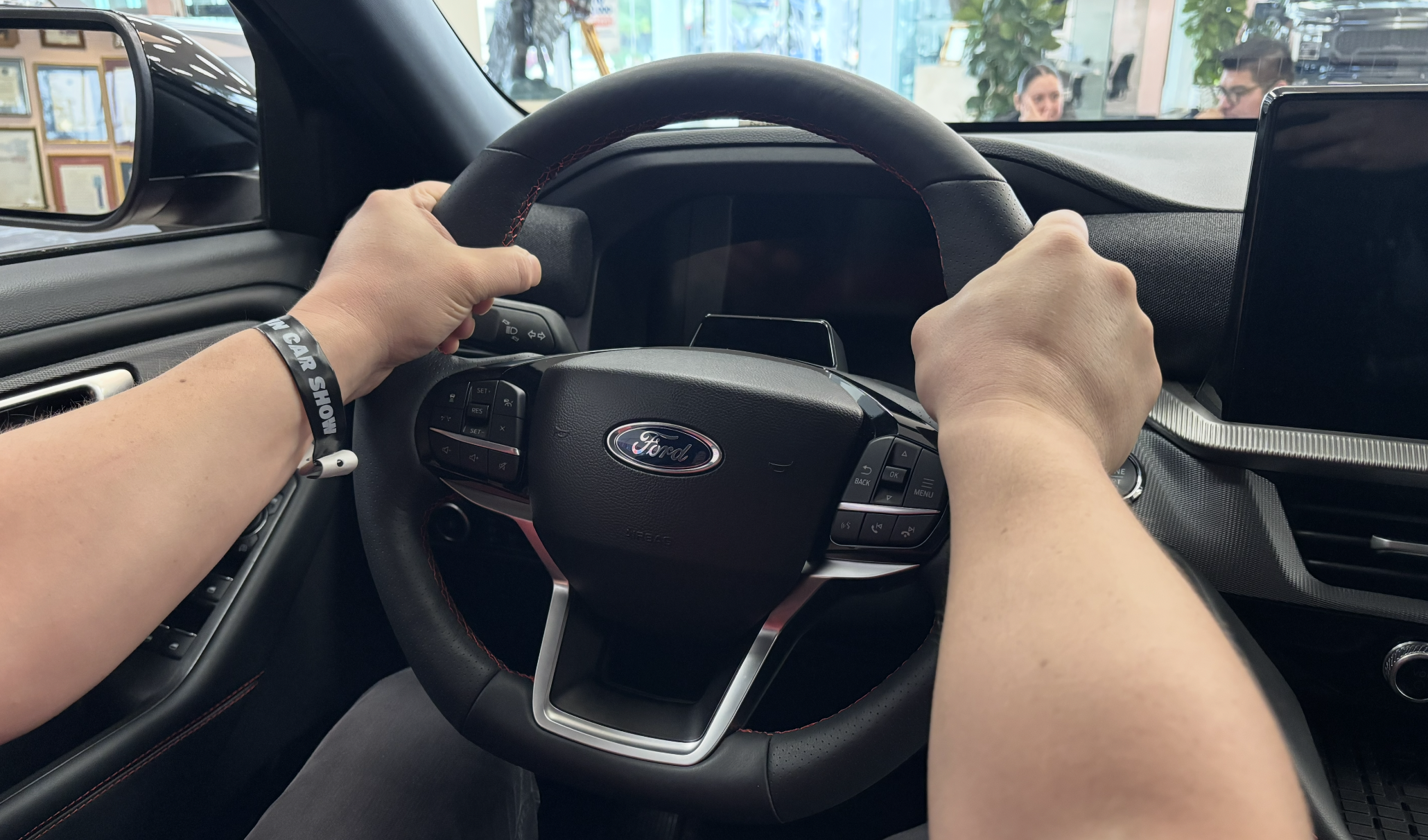
But what keeps the steering system from moving in response to the force pushing on the tie rods? The hands holding the steering wheel, of course!
Remember though, there is another suspension on the other side of the car, and as long as the drive forces on both sides of the car are the same, the forces acting on the two tie rods will be the same and they will cancel each other out and the net force on the steering system will be zero.
But what happens if the drive forces on the left and right suspensions are not the same? We then have a situation where the forces in the left and right tie rods are also not the same and there will be a net force on the steering system. The driver’s hands will then be the only thing keeping the steering wheel from turning. This is what you feel when you get torque steer generated by unequal left and right drive forces.
Suspension Design Impact
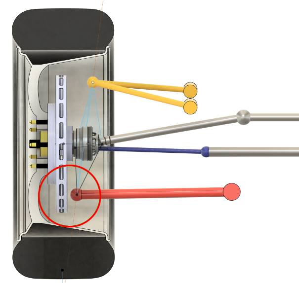
So, what can suspension design engineers do to help this situation? Unfortunately, while we can reduce the effect, it is basically impossible to eliminate it altogether. Think back to our door example. The door didn’t move when we pushed directly on the hinge axis. We could theoretically do this in a suspension by having the road “push” directly on the kingpin axis, but this would mean the kingpin axis would have to pass through the center of the wheel. That is theoretically possible, but in practice it is not. This is because there are many competing factors that go into determining where the ball joints in a suspension can be located. The main one is brakes. We need brakes, and they take up a lot of space inside the wheel. As you can see here, the brakes limit how far outboard we can push the lower ball joint:
We could use inboard brakes, which has been done in the past, but that creates other problems. Brakes are big, and if we put them at the inboard side of the halfshafts, they would likely stick out through the bottom of the car. We could move the whole engine/transmission assembly up to get the brakes higher, but that creates other problems with halfshaft angles which we’ll discuss later.
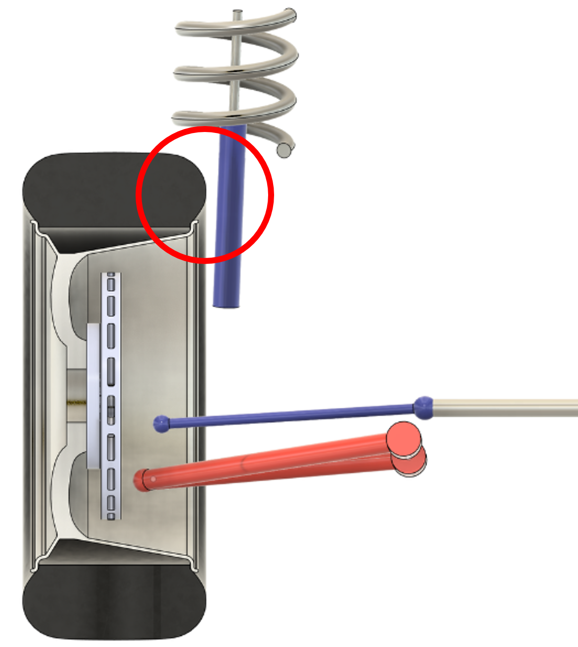
In a MacPherson strut, we have the added complication that the damper/spring can only move outboard so much before they hit the tire:
If we wanted to place the kingpin axis through the center of the wheel in this case, the lower ball joint would have to be almost outside the wheel:
There are other factors involved in choosing where the kingpin axis can go, such as camber-in-turn, steering returnability, and scrub radius, which gets into how braking forces impact the steering system. Suffice it to say that when you put all this together, placing the kingpin axis through the center of the wheel becomes for all intents and purposes impossible.
The result is that there will always be some kingpin offset, but we can do things to minimize it. Double wishbone suspensions make this a little easier because the upper balljoint can be placed further outboard than the top of a MacPherson strut can. We can also use a split lower arm to “project” the lower ball joint further outboard than the brakes might allow. You can see how this “double balljoint” (which has a virtual steering axis and which has been utilized across the industry from BMW sedans to Teslas to Chrysler L-cars) works here.
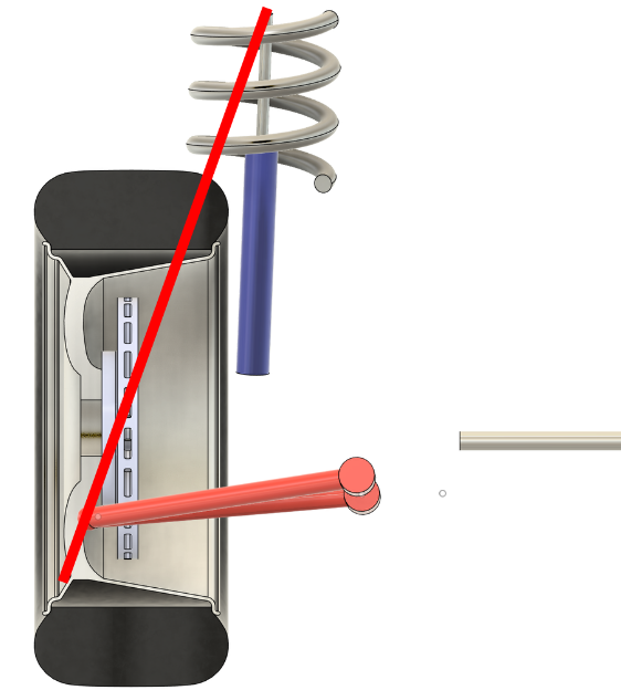
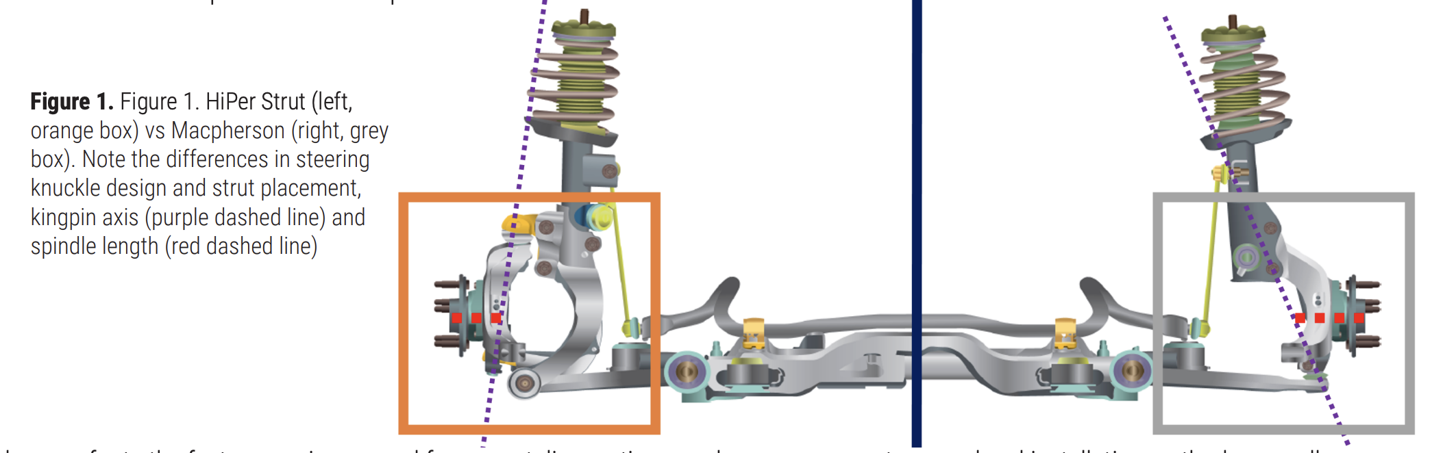
Another design trick some manufacturers have used is to add a secondary knuckle to their MacPherson struts. This means the strut does not rotate with the steering system anymore and the kingpin axis is much further outboard. GM did it with its HiPer Strut:
Ford did it with the Revo Knuckle:
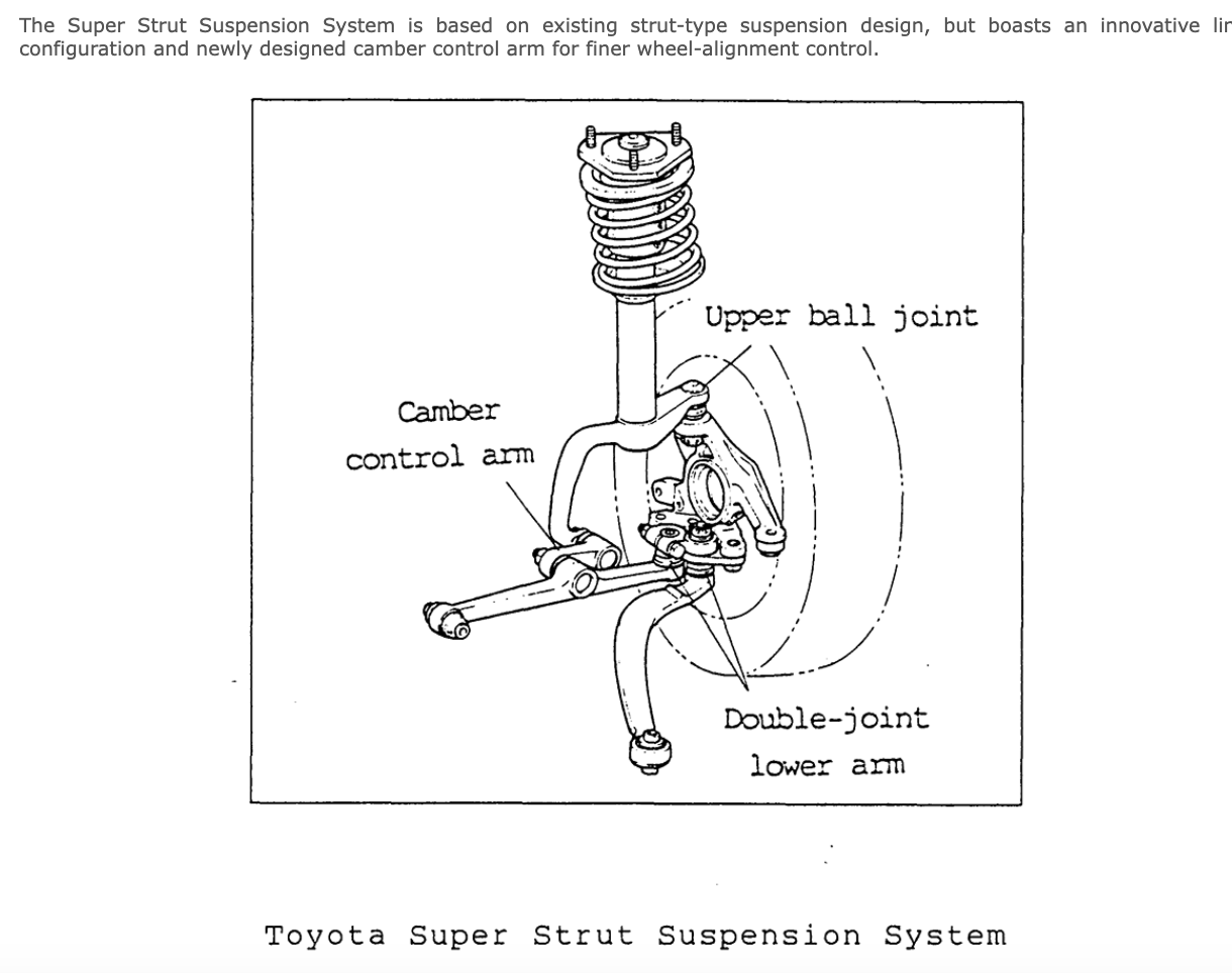
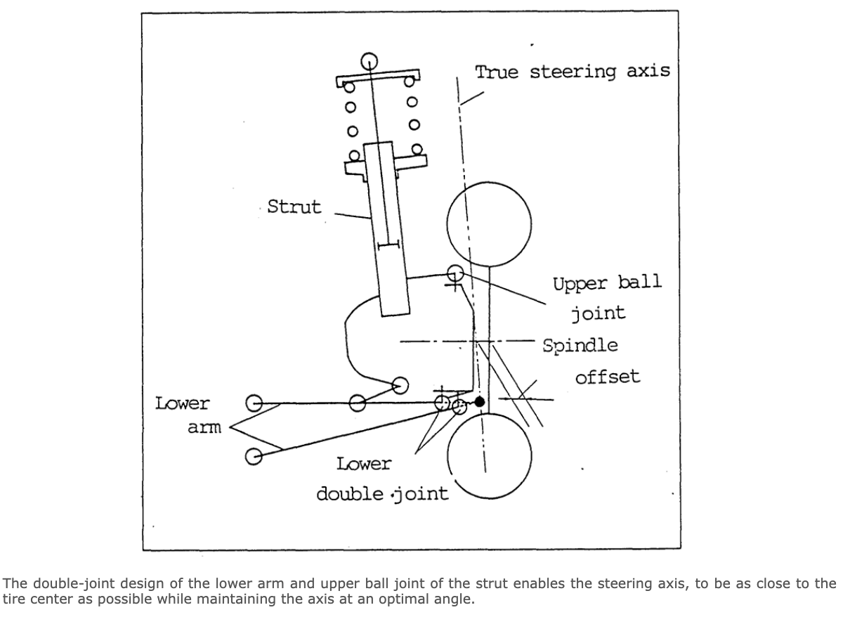
and Toyota with its SuperStrut:
Differential Design
I mentioned earlier that there are things we can do with the differential design that can help here as well.
The standard open differential design is such that it is virtually impossible for it to apply unequal torque to the left and right halfshafts even if the traction levels under the left and right tires are vastly different. This is because the engine torque is transferred to the side gears attached to each halfshaft via the drive gears which are inside the carrier.
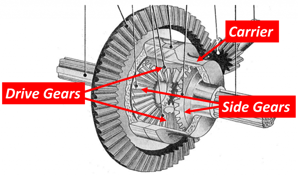
Image via: Public Doman/ Differential (mechanical device) – Wikipedia
If the side gears try to transfer different levels of torque to the left and right halfshafts, they will just spin. It means that it is not possible to push on one of the side gears harder than the other. It means the drive torques on the left and right sides will always be the same and no torque steer will be generated in this way, barring slight differences in friction in the whole system. It also means the torque this type of differential will transmit to the wheels is limited by the side with the least amount of traction. Ideal from a torque steer perspective, but not ideal from a traction and tractive capability perspective.
This video does an excellent job of explaining why this is true: (55) Open vs Locked Differential – Torque Transfer – Explained – YouTube
One possible solution would be to use some sort of limited slip differential using clutch packs or a Torsen design. Either of these would solve the traction problem, but it would do so by sending more torque to the side that has the traction. This means there will be unequal amounts of torque going to the left and right suspensions. The car will accelerate a lot better, but there will be a lot of torque steer for the driver to contend with under those circumstances.
Unequal CV Joint Angles
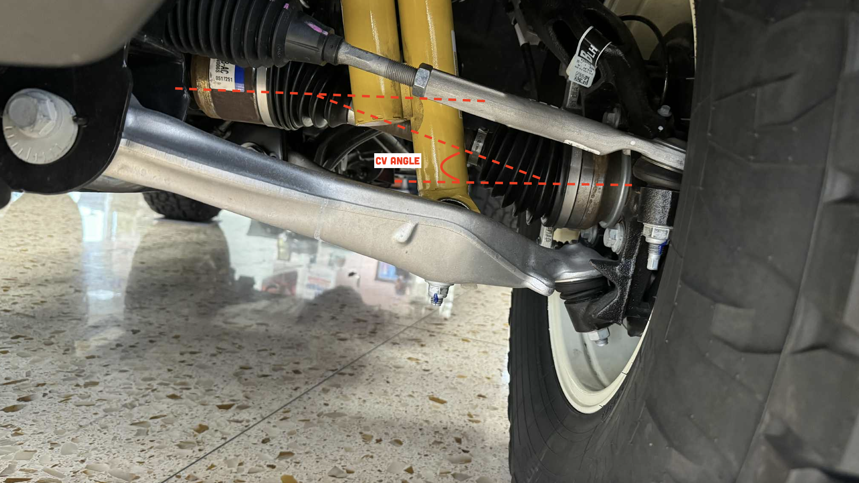
Now let’s talk about the second mechanism for generating torque steer: unequal CV joint angles.
You may have heard in the past about a car having equal length halfshafts and wondered why they were making such a big deal about it. It gets into the angles of the left and right outer CV joints and how they compare with each other. To understand this, we will need to get a bit nerdy.
We first need to understand what a torque vector is.
Torque Vectors
When engineers talk about the torque that is spinning an object, like a halfshaft, they use a vector to show the direction and magnitude of the torque. To illustrate the vector, they use an arrow. To draw this arrow, engineers use something called the Right Hand Rule. Here is how it works.
Right Hand Rule
Imagine a spinning shaft. Now, take your right hand and curl your fingers in the direction the shaft is spinning. Next, stick out your thumb. The direction your thumb is pointing is the direction of the arrow engineers draw to represent the torque.
It is important to note here that the direction of the arrow is important but the size is random. If there were multiple torques that we were talking about in the same mechanism, we would use the relative size of each arrow to represent the relative sizes of the torques. For example, an arrow that is twice as long as another would represent a torque that is twice as big.
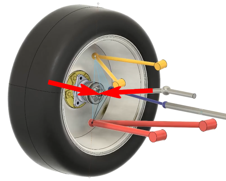
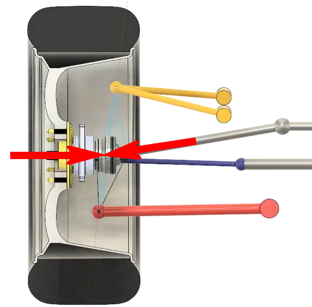
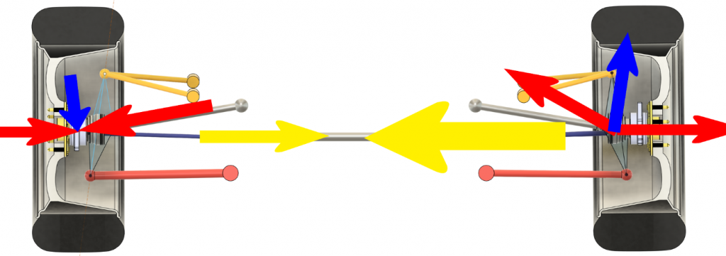
So, how do we use this concept to understand what is going on in our suspension? Let’s go back to our double wishbone model and include a halfshaft. Now imagine the car is stopped and we hit the accelerator. Instantaneously, the engine develops torque and sends it down the halfshaft to the wheel. If we look at the left side suspension (so in the picture, the front of the vehicle would be to the top right) and apply the right hand rule we just learned, we see that this torque would be represented by an arrow pointing to the outer CV joint. (Note: The blue is the steering tie rod; the CV axle is above it with the arrow at its end):
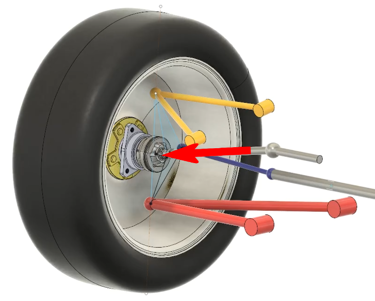
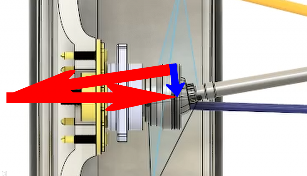
At the same time, the wheel is pushing back on this with an equal and opposite torque also represented by an arrow pointing to the CV joint.
Since both arrows point to the center of the CV joint, they form a plane, unless they just happen to be directly in line with each other, which is possible, but highly unlikely.
If we look directly at this plane, we can now do something with our vectors called vector addition.
However, with vector addition, the vectors must be head to tail, not head to head like we have. We first re-arrange the vectors to place them head to tail and now we can draw a new vector from the tail of the first one to the head of the second one. [Ed Note: This head-to-tail thing is just an engineering trick to help you visualize the direction of the resulting torque. -DT].
This new vector represents the sum of the first two vectors, and it lies in the same plane. If we now apply the right hand rule on this new vector, we see that it represents a torque trying to steer the knuckle to the right (look at how my fingers curl in the gif below). It gives the suspension a toe-in moment.
Notice also that the larger the angle between the original vectors, the larger the sum vector becomes and the more toe-in torque we would get on the knuckle.
If we now look at the left and right suspensions together, we see that the same but opposite thing is happening on the right side. Both suspensions are trying to toe in, and since the magnitude of the toe in moment depends on the angle of the CV joints, as long as the angles in the left and right CV joints are the same, the toe-in moments will be the same and they will cancel each other out through the steering system.

Note that in the image above, the yellow arrows do not represent another torque but instead represent the forces of the left and right suspensions pushing on the steering system.
On the other hand, if the angles of the left and right outer CV joints are NOT the same, then the two yellow arrows will not be the same size, and there will be a net force on the steering system.
So, what can suspension and driveline engineers do to prevent unequal CV joint angles from happening? Since we are dealing with torques, not forces, there are no offsets we can change like we did with the kingpin offset we played with earlier. All we can do is to try to keep those blue torque arrows coming from the left and right suspensions the same or close, and we do that by making sure the left and right outer CV joint angles are the same (or close) as much and as often as possible. The best way we can do this to use equal length halfshafts. Let’s look at the complete driveline to see how this works.
In almost all front wheel drive cars, the powertrain is placed in a sideways orientation with the engine on the right side of the car and the transmission on the left (this has to do with the traditional direction an engine spins, though this isn’t unifrom). This means the differential is offset to the left side of the car. If we add halfshafts straight from the differential to each knuckle, we can see that the right shaft will be longer than the left. If the engine is placed higher than the center of the wheel, which it often is, then there will be a downward angle on the halfshafts. Since the right shaft is longer, it means that the angle at the right side CV joint will be less than the left.
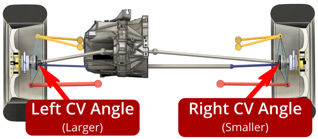
It gets worse as the car accelerates due to lift at the front of the car. This lift increases the outer CV joint angles on both sides, but because of the shorter shaft length, they get worse faster on the left than the right. This is a guaranteed recipe for torque steer and is the reason many early front wheel drive cars suffered from this issue.
Driveline engineers quickly figured this out and instead of using a single halfshaft on the right side, added what’s known as a “jack shaft” (basically like a spacer), which placed the inner right side CV joint in the symmetrically opposite position as the left.
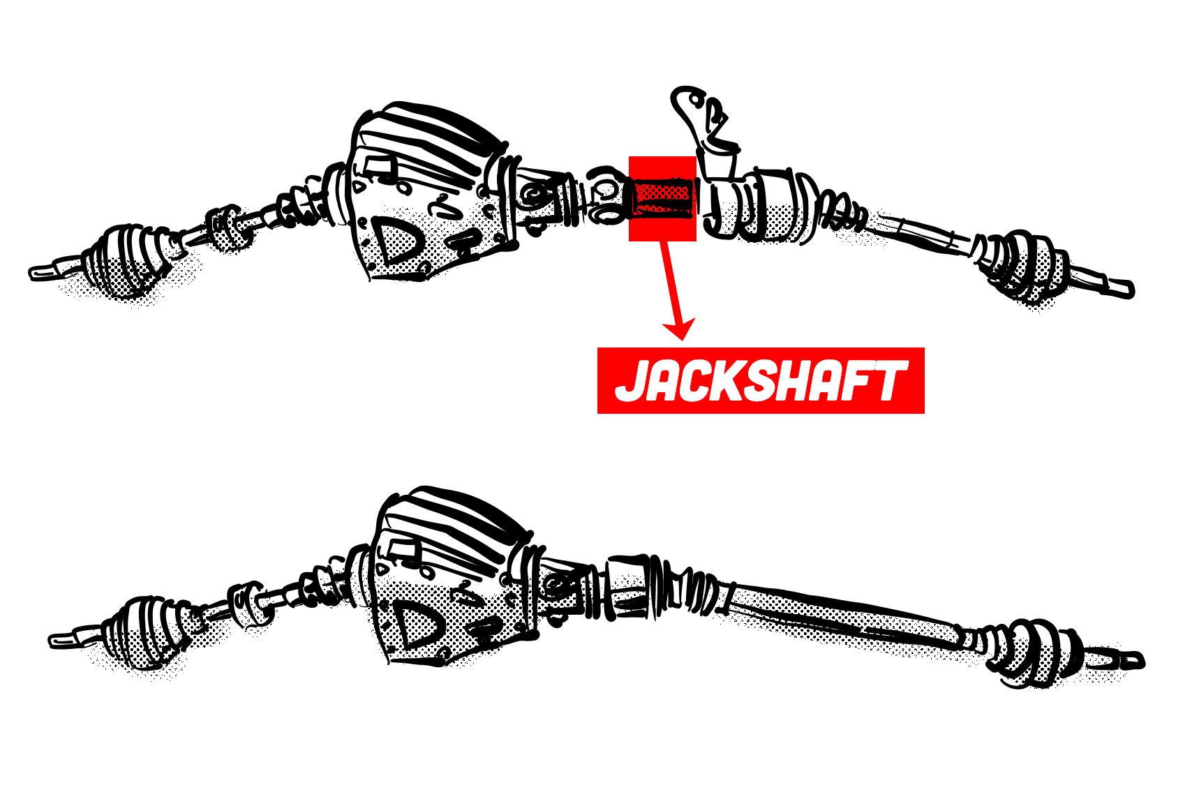
This means that the right side halfshaft going to the knuckle was the same length as the left and therefore had the same angle at the outer CV joint.

If you’ve ever heard the term “equal length halfshafts,” this is what they were talking about.
What About Cornering?
Of course, this is all well and good in straight line acceleration where the left and right suspensions are doing the same thing, but there are situations where that is not the case. In cornering for example, the outside suspension will be higher relative to the body while the inner suspension will be lower. The outer CV joint angles will be commensurately different in that case and that difference is going to generate torque steer.
Also, if you are accelerating over an undulating surface, the left and right suspensions will be at different heights, which will be changing constantly. This will result in constantly changing torque vectors coming from the left and right sides and there is little we can do about it. It’s why high horsepower front wheel drive cars often feel like they’re squirming around under acceleration over anything except a perfectly smooth road. It’s also why torque steer will always be a problem when accelerating while cornering.
The only fix would be to make the springs very stiff so that there is little body roll in cornering or movement in the suspension over road undulations. Or course, this makes for a rather uncomfortable ride so it’s not a very desirable solution.
There are things modern cars with electric power steering can do however. It is possible to program the steering to counteract the torque steer forces coming from the suspension, but this is really just a band-aid and will likely impact steering feel and feedback, something most enthusiasts would not want to compromise.
Rear Wheel Drive
So far, we’ve only talked about front wheel drive. Torque steer can be an issue in rear wheel drive as well, but since there is usually not an engine back there, it is pretty easy to keep the differential centrally mounted and have equal length halfshafts. Also, because the rear suspension is not connected to the steering system, it is able to counteract any torque steer without impacting the driver.


Honestly the only reason I want a RWD based automobile nowadays is for power sliding.
Otherwise I believe FWD based is the way to go the overwhelming majority of the time.
FWD based 4WD is my favorite layout.