
If you’ve been around this crazy automotive world as long as I have (my ample grey hairs prove this to be true), you will probably remember the early days of front-wheel drive cars. If you ever drove one of these cars, you will probably also remember a problem many of them had that caused them to steer all by themselves whenever you hit the gas pedal. It’s called “Torque Steer,” and it is something no FWD car is immune to, even today.
So, what is Torque Steer, how is it generated, and are there things suspension engineers can do to eliminate or at least mitigate it? Let’s dive in.
[Ed Note: Welcome back our resident suspension engineer, Huibert Mees. He took a bit of a break, because he deserves one after developing the Ford GT’s and Tesla Model S’s suspension. -DT].
A Little History
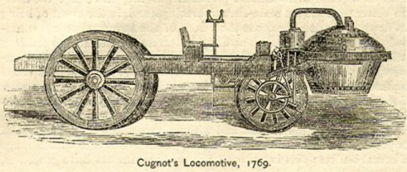
Front wheel drive cars have been around for a long time. You could say that it is the original drivetrain configuration since the very first self-powered vehicle, the gun tractor built by Nicholas Cugnot in 1769, used it.
Driving a single front wheel is one thing, but as automotive design settled on 4 wheels, the technical challenges of getting the drive torque to two wheels that also had to steer kept front wheel drive from becoming the norm that it is today. That’s not to say some didn’t try. Cord famously used it in 1929 for the L-29.
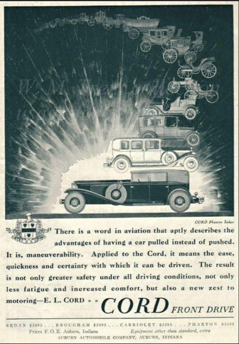
Unfortunately, the perception that the L-29’s top speed of 80 mph was a bit tame, as well as the looming depression that started right after the car was introduced, kept it from being a commercial success. It’s a shame, really, because these cars are stunning and much sought after today.
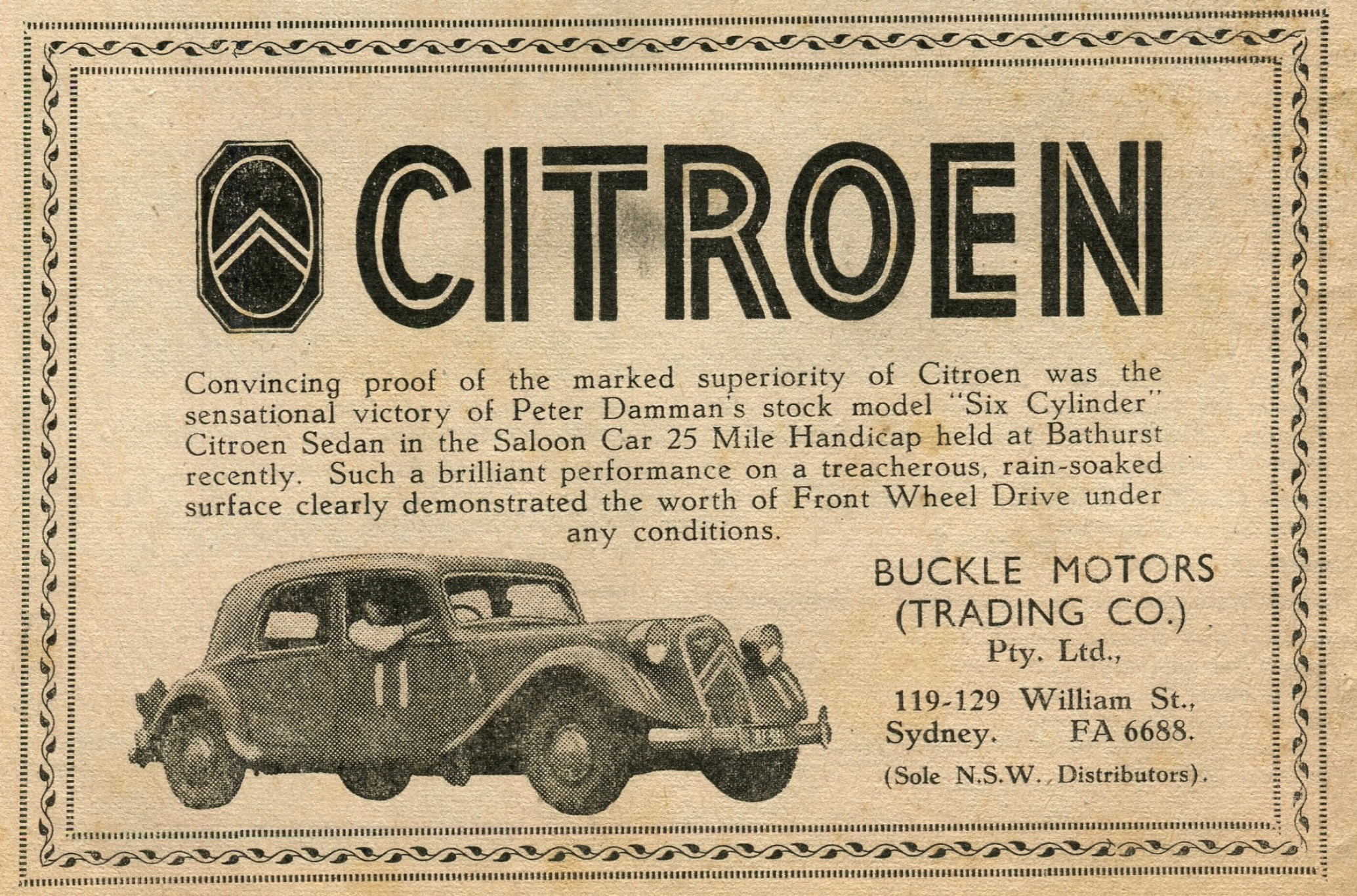
A few years later, Citroen would have a go at it with the Traction-Avant, which literally means “front drive.” This time, however, it proved to be a much bigger success, with production peaking at just under 20,000 cars in 1936. If you want to see one of these in action (and hear some gorgeous music), watch the film Diva.
After the success of the Traction Avant, Citroen would go on to use front wheel drive in most of its subsequent models. GM would also make a go of it in the mid 60’s with the chain-driven Oldsmobile Toronado and the Cadillac Eldorado, but these were relatively niche vehicles.
As far as the general automotive market goes, front wheel drive didn’t take off until the 70’s after the 1973 oil shock sent many customers looking for smaller, more efficient cars. Japanese manufacturers like Honda and Toyota had just the ticket: small front wheel drive cars. Since these cars were small, space was at a premium. Anything to get more interior room for passengers and cargo made them more appealing. Front wheel drive, with its lack of a large central tunnel to package a driveshaft made it ideal for these types of cars. Compare a Chevy Vega or a Ford Pinto with a Honda Civic or Accord from this era and you will see the advantages of the front wheel drive configuration on interior space.
Over time, front wheel drive became the norm for anything except high end luxury and sports cars and as it became more accepted, the demand for more powerful engines started to increase. These more powerful engines exposed a problem previously masked by the lack of power of the earlier cars: torque steer.
What is Torque Steer?
Torque steer is a phenomenon in which some aspect of the drivetrain design — or the road and driving conditions — cause the car to steer by itself, right or left, under hard acceleration. It can happen in either front wheel drive or rear wheel drive cars, but it is most prevalent with front wheel drive since the drive wheels are attached to the steering system.
So, how is torque steer generated and is there anything we can do in the design of the car to eliminate it?
Torque Steer Mechanisms
There are two basic ways in which torque steer can be generated: un-equal application of drive forces at the left and right wheels, and un-equal left and right halfshaft outer constant velocity (CV) joint angles.
Let’s talk about each of these starting with un-equal application of drive forces to the left and right wheels.
Un-Equal Drive Forces
As torque travels from the engine through the transmission, it passes through the differential and is split between the left and right halfshafts. In a standard “open” differential, the torque is split evenly between the left and right sides. The open differential design ensures that both halfshafts always get the same amount of torque, regardless of tire friction.
The torque travels down the halfshafts, through the wheel bearings attached to the knuckles and into the wheels and tires. The friction between the tires and the road converts the torque into a force, which propels the vehicle forward. As long as the friction levels between road and the left and right tires are similar, the forward force generated by this friction will be about the same left and right.
However, if the friction levels between the left and right tires are very different, such as when one tire is on ice or wet leaves, then the tractive capability of the tires will not be the same. Here is where the design of the suspension and the differential come into play.
If we look at a generic double wishbone suspension, we see that the axis the suspension steers around is defined by a line through the upper and lower ball joints.
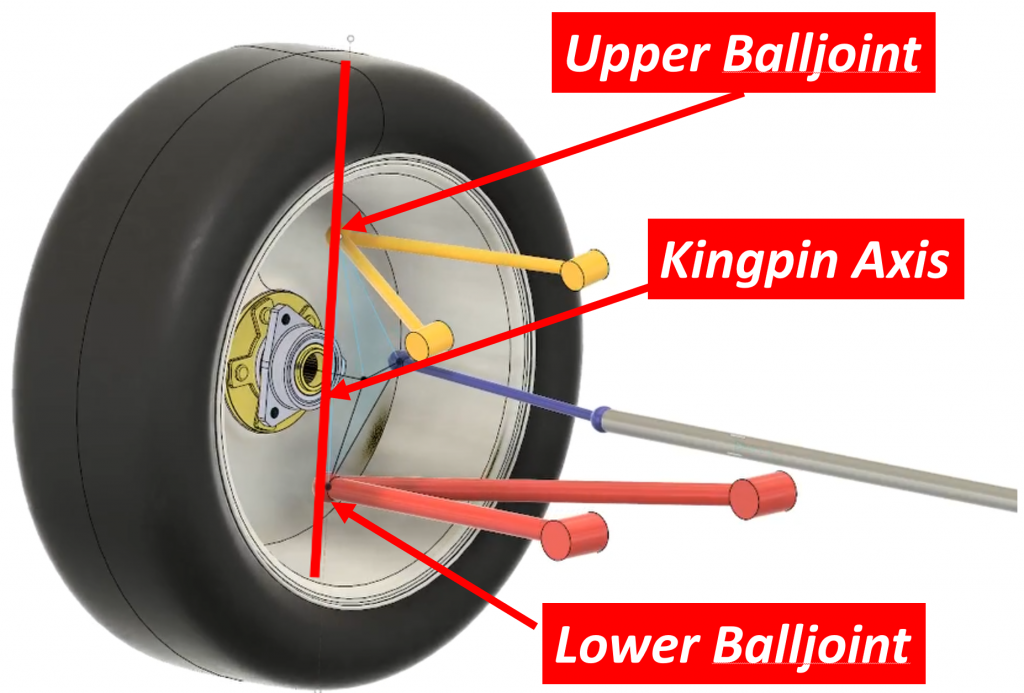
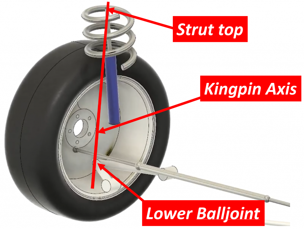
This axis is called the steer axis or kingpin axis. In a MacPherson strut it is defined by the lower balljoint and the top of the strut:
This axis functions like the hinge axis of a door. The door rotates about the hinge axis when you open and close is just like the wheel rotates about the kingpin axis when you steer it.
Now, let’s look at where the tractive force is applied. If we think of the vehicle as a whole, the force accelerating the car is generated between the tires and the road. This means the force pulling the car forward is located at the tire contact patch.

However, in order to understand torque steer, we need to look at it from the perspective of just the suspension, not the total vehicle. When we do that, we see that the torque traveling down the halfshafts passes through the knuckle via the bearing. As the torque passes through the bearing, the part of the bearing attached to the outer CV joint just spins while the outer housing of that bearing (a housing that is attached to the knuckle) sits there stationary. There is essentially no torque transfer between the halfshafts and the knuckle. There is, on the other hand, a force that happens between the bearing and the knuckle. As the wheel spins, thanks to the tire’s traction with the ground, it “pushes” the vehicle (and suspension) forward through that bearing, but since the bearing can only transfer a force to the knuckle, as far as the knuckle is concerned, this force happens at the center of the wheel.

It is critical to fully grasp this because the location of the drive force on the suspension is central to how the suspension, and the steering system, react to it.
Let’s go back to our suspension model to see what this all means, because as you can see here, it’s pretty intuitive — the car moves because the road is effectively “pushing” the car forward through the wheel, which is connected to the rest of the car via that bearing in the knuckle.
When we add an arrow representing the drive force to our model…

…we see that there is an offset between this arrow and the kingpin axis.

It’s a little hard to see since it’s a 3-dimensional problem, but this offset is called the “kingpin offset.”Suspension engineers spend a lot of time trying to get this distance down to a minimum, but as we’ll see later, there are limitations on how small it can get.
What the kingpin offset means is that the drive force is pushing on the suspension not directly on the steering axis, but at some distance away from it. Imagine pushing on a door right at the hinge axis. The door wouldn’t move. If, on the other hand, you push on the door some distance away from the hinges, the door will move, and the farther away from the hinge axis you push, the easier it is to make the door move.
The same goes for a suspension. The larger the kingpin offset, the more the drive forces try to make the suspension steer. But the suspension can’t steer by itself because it is connected to the steering system through the tie rods.
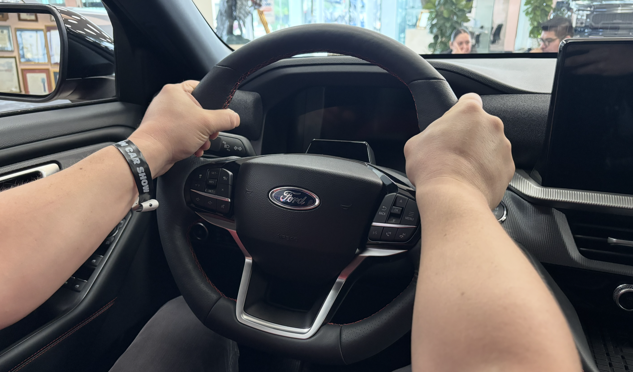
But what keeps the steering system from moving in response to the force pushing on the tie rods? The hands holding the steering wheel, of course!
Remember though, there is another suspension on the other side of the car, and as long as the drive forces on both sides of the car are the same, the forces acting on the two tie rods will be the same and they will cancel each other out and the net force on the steering system will be zero.
But what happens if the drive forces on the left and right suspensions are not the same? We then have a situation where the forces in the left and right tie rods are also not the same and there will be a net force on the steering system. The driver’s hands will then be the only thing keeping the steering wheel from turning. This is what you feel when you get torque steer generated by unequal left and right drive forces.
Suspension Design Impact
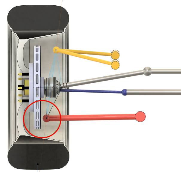
So, what can suspension design engineers do to help this situation? Unfortunately, while we can reduce the effect, it is basically impossible to eliminate it altogether. Think back to our door example. The door didn’t move when we pushed directly on the hinge axis. We could theoretically do this in a suspension by having the road “push” directly on the kingpin axis, but this would mean the kingpin axis would have to pass through the center of the wheel. That is theoretically possible, but in practice it is not. This is because there are many competing factors that go into determining where the ball joints in a suspension can be located. The main one is brakes. We need brakes, and they take up a lot of space inside the wheel. As you can see here, the brakes limit how far outboard we can push the lower ball joint:
We could use inboard brakes, which has been done in the past, but that creates other problems. Brakes are big, and if we put them at the inboard side of the halfshafts, they would likely stick out through the bottom of the car. We could move the whole engine/transmission assembly up to get the brakes higher, but that creates other problems with halfshaft angles which we’ll discuss later.
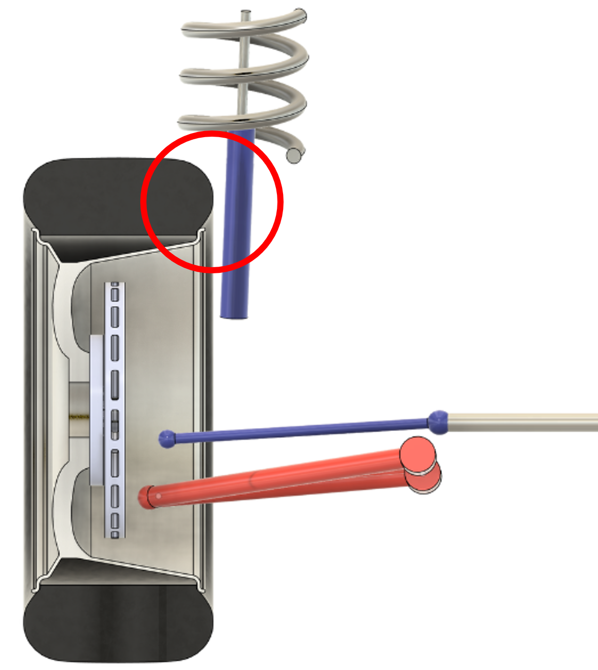
In a MacPherson strut, we have the added complication that the damper/spring can only move outboard so much before they hit the tire:
If we wanted to place the kingpin axis through the center of the wheel in this case, the lower ball joint would have to be almost outside the wheel:
There are other factors involved in choosing where the kingpin axis can go, such as camber-in-turn, steering returnability, and scrub radius, which gets into how braking forces impact the steering system. Suffice it to say that when you put all this together, placing the kingpin axis through the center of the wheel becomes for all intents and purposes impossible.
The result is that there will always be some kingpin offset, but we can do things to minimize it. Double wishbone suspensions make this a little easier because the upper balljoint can be placed further outboard than the top of a MacPherson strut can. We can also use a split lower arm to “project” the lower ball joint further outboard than the brakes might allow. You can see how this “double balljoint” (which has a virtual steering axis and which has been utilized across the industry from BMW sedans to Teslas to Chrysler L-cars) works here.
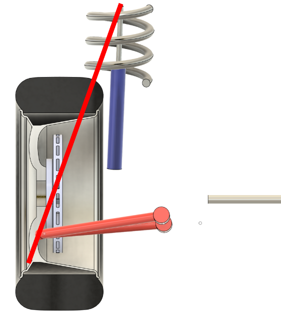
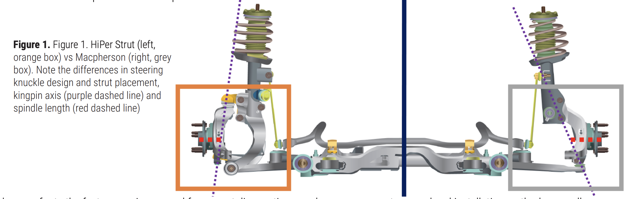
Another design trick some manufacturers have used is to add a secondary knuckle to their MacPherson struts. This means the strut does not rotate with the steering system anymore and the kingpin axis is much further outboard. GM did it with its HiPer Strut:
Ford did it with the Revo Knuckle:
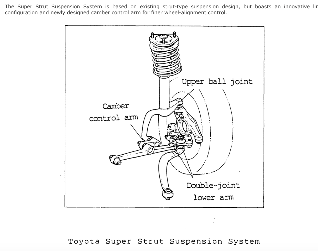
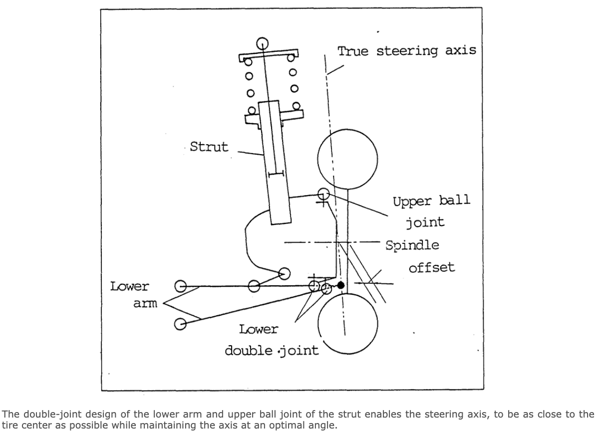
and Toyota with its SuperStrut:
Differential Design
I mentioned earlier that there are things we can do with the differential design that can help here as well.
The standard open differential design is such that it is virtually impossible for it to apply unequal torque to the left and right halfshafts even if the traction levels under the left and right tires are vastly different. This is because the engine torque is transferred to the side gears attached to each halfshaft via the drive gears which are inside the carrier.
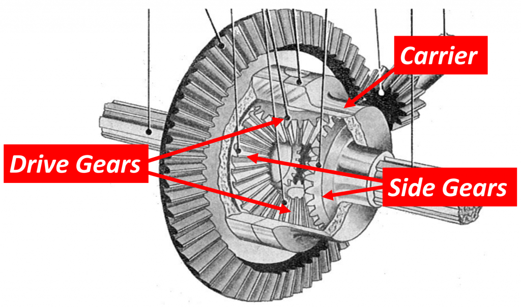
Image via: Public Doman/ Differential (mechanical device) – Wikipedia
If the side gears try to transfer different levels of torque to the left and right halfshafts, they will just spin. It means that it is not possible to push on one of the side gears harder than the other. It means the drive torques on the left and right sides will always be the same and no torque steer will be generated in this way, barring slight differences in friction in the whole system. It also means the torque this type of differential will transmit to the wheels is limited by the side with the least amount of traction. Ideal from a torque steer perspective, but not ideal from a traction and tractive capability perspective.
This video does an excellent job of explaining why this is true: (55) Open vs Locked Differential – Torque Transfer – Explained – YouTube
One possible solution would be to use some sort of limited slip differential using clutch packs or a Torsen design. Either of these would solve the traction problem, but it would do so by sending more torque to the side that has the traction. This means there will be unequal amounts of torque going to the left and right suspensions. The car will accelerate a lot better, but there will be a lot of torque steer for the driver to contend with under those circumstances.
Unequal CV Joint Angles
Now let’s talk about the second mechanism for generating torque steer: unequal CV joint angles.
You may have heard in the past about a car having equal length halfshafts and wondered why they were making such a big deal about it. It gets into the angles of the left and right outer CV joints and how they compare with each other. To understand this, we will need to get a bit nerdy.
We first need to understand what a torque vector is.
Torque Vectors
When engineers talk about the torque that is spinning an object, like a halfshaft, they use a vector to show the direction and magnitude of the torque. To illustrate the vector, they use an arrow. To draw this arrow, engineers use something called the Right Hand Rule. Here is how it works.
Right Hand Rule
Imagine a spinning shaft. Now, take your right hand and curl your fingers in the direction the shaft is spinning. Next, stick out your thumb. The direction your thumb is pointing is the direction of the arrow engineers draw to represent the torque.
It is important to note here that the direction of the arrow is important but the size is random. If there were multiple torques that we were talking about in the same mechanism, we would use the relative size of each arrow to represent the relative sizes of the torques. For example, an arrow that is twice as long as another would represent a torque that is twice as big.
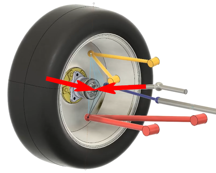
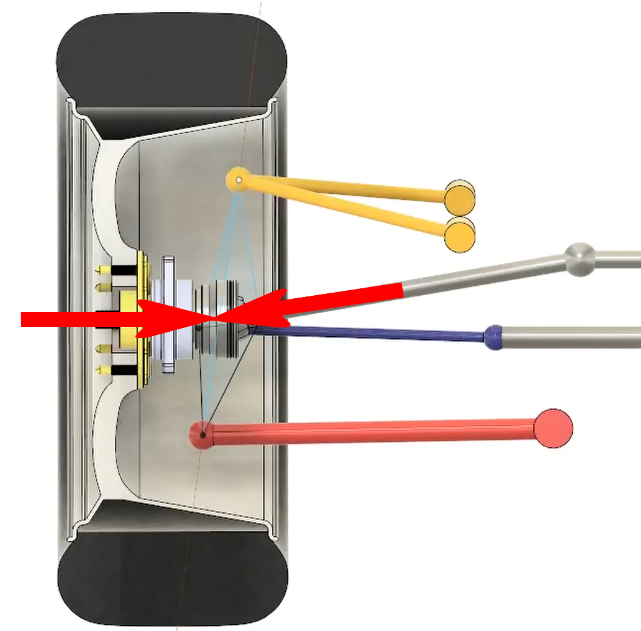
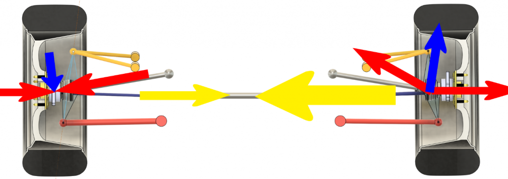
So, how do we use this concept to understand what is going on in our suspension? Let’s go back to our double wishbone model and include a halfshaft. Now imagine the car is stopped and we hit the accelerator. Instantaneously, the engine develops torque and sends it down the halfshaft to the wheel. If we look at the left side suspension (so in the picture, the front of the vehicle would be to the top right) and apply the right hand rule we just learned, we see that this torque would be represented by an arrow pointing to the outer CV joint. (Note: The blue is the steering tie rod; the CV axle is above it with the arrow at its end):
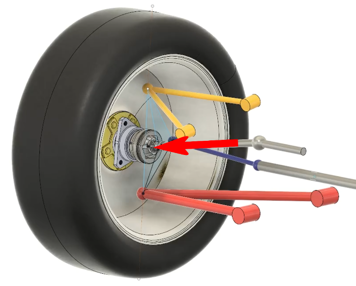
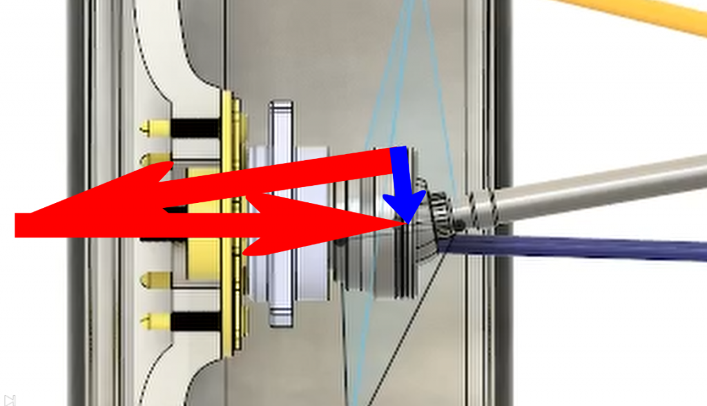
At the same time, the wheel is pushing back on this with an equal and opposite torque also represented by an arrow pointing to the CV joint.
Since both arrows point to the center of the CV joint, they form a plane, unless they just happen to be directly in line with each other, which is possible, but highly unlikely.
If we look directly at this plane, we can now do something with our vectors called vector addition.
However, with vector addition, the vectors must be head to tail, not head to head like we have. We first re-arrange the vectors to place them head to tail and now we can draw a new vector from the tail of the first one to the head of the second one. [Ed Note: This head-to-tail thing is just an engineering trick to help you visualize the direction of the resulting torque. -DT].
This new vector represents the sum of the first two vectors, and it lies in the same plane. If we now apply the right hand rule on this new vector, we see that it represents a torque trying to steer the knuckle to the right (look at how my fingers curl in the gif below). It gives the suspension a toe-in moment.
Notice also that the larger the angle between the original vectors, the larger the sum vector becomes and the more toe-in torque we would get on the knuckle.
If we now look at the left and right suspensions together, we see that the same but opposite thing is happening on the right side. Both suspensions are trying to toe in, and since the magnitude of the toe in moment depends on the angle of the CV joints, as long as the angles in the left and right CV joints are the same, the toe-in moments will be the same and they will cancel each other out through the steering system.

Note that in the image above, the yellow arrows do not represent another torque but instead represent the forces of the left and right suspensions pushing on the steering system.
On the other hand, if the angles of the left and right outer CV joints are NOT the same, then the two yellow arrows will not be the same size, and there will be a net force on the steering system.
So, what can suspension and driveline engineers do to prevent unequal CV joint angles from happening? Since we are dealing with torques, not forces, there are no offsets we can change like we did with the kingpin offset we played with earlier. All we can do is to try to keep those blue torque arrows coming from the left and right suspensions the same or close, and we do that by making sure the left and right outer CV joint angles are the same (or close) as much and as often as possible. The best way we can do this to use equal length halfshafts. Let’s look at the complete driveline to see how this works.
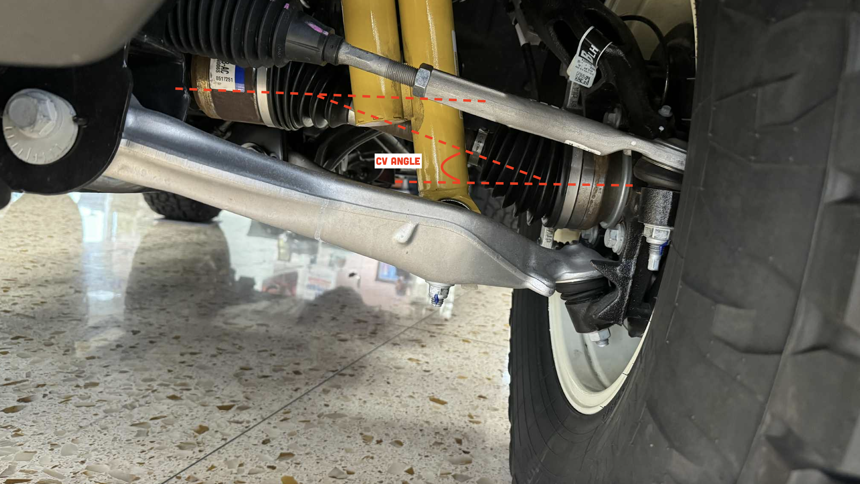
In almost all front wheel drive cars, the powertrain is placed in a sideways orientation with the engine on the right side of the car and the transmission on the left (this has to do with the traditional direction an engine spins, though this isn’t unifrom). This means the differential is offset to the left side of the car. If we add halfshafts straight from the differential to each knuckle, we can see that the right shaft will be longer than the left. If the engine is placed higher than the center of the wheel, which it often is, then there will be a downward angle on the halfshafts. Since the right shaft is longer, it means that the angle at the right side CV joint will be less than the left.
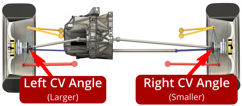
It gets worse as the car accelerates due to lift at the front of the car. This lift increases the outer CV joint angles on both sides, but because of the shorter shaft length, they get worse faster on the left than the right. This is a guaranteed recipe for torque steer and is the reason many early front wheel drive cars suffered from this issue.
Driveline engineers quickly figured this out and instead of using a single halfshaft on the right side, added what’s known as a “jack shaft” (basically like a spacer), which placed the inner right side CV joint in the symmetrically opposite position as the left.
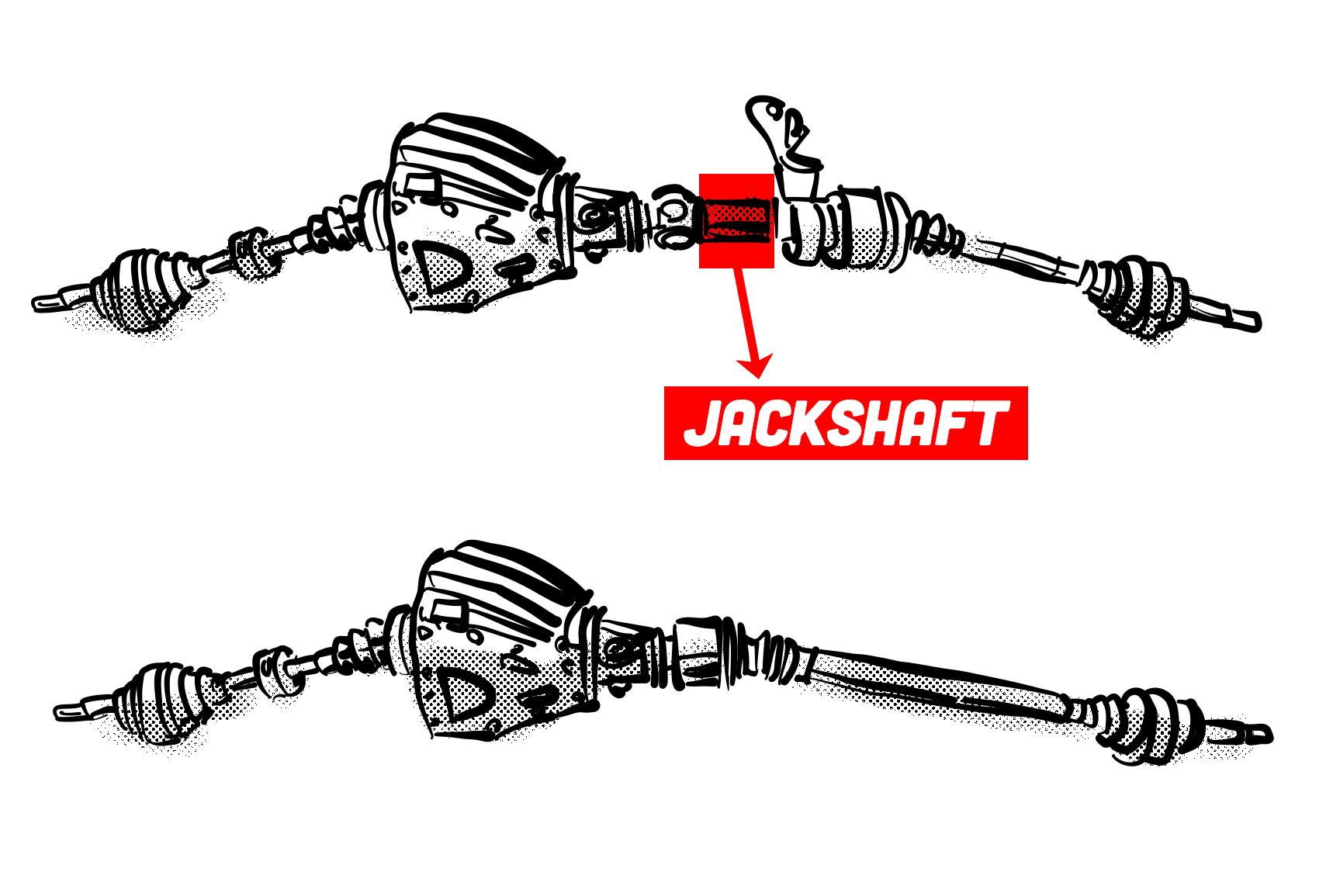
This means that the right side halfshaft going to the knuckle was the same length as the left and therefore had the same angle at the outer CV joint.

If you’ve ever heard the term “equal length halfshafts,” this is what they were talking about.
What About Cornering?
Of course, this is all well and good in straight line acceleration where the left and right suspensions are doing the same thing, but there are situations where that is not the case. In cornering for example, the outside suspension will be higher relative to the body while the inner suspension will be lower. The outer CV joint angles will be commensurately different in that case and that difference is going to generate torque steer.
Also, if you are accelerating over an undulating surface, the left and right suspensions will be at different heights, which will be changing constantly. This will result in constantly changing torque vectors coming from the left and right sides and there is little we can do about it. It’s why high horsepower front wheel drive cars often feel like they’re squirming around under acceleration over anything except a perfectly smooth road. It’s also why torque steer will always be a problem when accelerating while cornering.
The only fix would be to make the springs very stiff so that there is little body roll in cornering or movement in the suspension over road undulations. Or course, this makes for a rather uncomfortable ride so it’s not a very desirable solution.
There are things modern cars with electric power steering can do however. It is possible to program the steering to counteract the torque steer forces coming from the suspension, but this is really just a band-aid and will likely impact steering feel and feedback, something most enthusiasts would not want to compromise.
Rear Wheel Drive
So far, we’ve only talked about front wheel drive. Torque steer can be an issue in rear wheel drive as well, but since there is usually not an engine back there, it is pretty easy to keep the differential centrally mounted and have equal length halfshafts. Also, because the rear suspension is not connected to the steering system, it is able to counteract any torque steer without impacting the driver.


A very long time ago, my dad owned a Cord. He thought front wheel drive made it hard to steer. As always, I’m happy to see a recommendation to view “Diva.”
My level of understanding of automotive engineering has always been at the level of “engine spins clutch—>gears—>driveshaft—>differential—> wheels.” But then got very fuzzy, very fast. This article was pitched almost exactly at my level of understanding of physics (college freshman pre-med, several decades ago) and was simply fascinating.
I know an article like this isn’t easy to write. A lot of technical detail has to be understood at a deep level in order to translate it for a general audience. So I know this is a bigger ask than it looks like, but: “more, please!”
Maybe a look into the eldritch sorcery that is the differential?
Isn’t the picture of the lever arm due to king pin offset wrong? Shouldn’t it be measured at the contact patch to determine the leverage, not at the center of the wheel? That would also mean your exaggerated McPherson strut diagram is too exaggerated.
For example (remembering from my time as a Honda engineer in another life), early 90s Honda Civics have a slightly negative king pin offset without massive packaging issues. The same vintage Accords have a positive king pin offset.
It made for a huge stability difference when hard into the ABS with one side of the car on a grippy surface and the other on a slick surface. The negative king pin offset would help steer the Civic front tires a little towards the low friction side which helped to counteract the spinning moment created by the unequal braking force. The Accord was, ….something entirely different.
The large kingpin offset on the Accords also lead to them being very sensitive to any cyclic variation of brake torque causing steering wheel shimmy.
You are correct in your thinking but remember that you are talking about braking. I’m talking about acceleration. The forces work differently. In an independent suspension with outboard brakes, braking forces are applied at the contact patch while acceleration forces are applied at the wheel center.
I think the real “Technical Reason Why Front-Wheel Drive Cars Sometimes Suck” is that minivans are often front-wheel drive, and occasionally include built-in vacuums, which, of course, sometimes suck
So is it pretty much just packaging that prevents inboard brakes from being more common? It seems like it would have some huge advantages for suspension geometry and unsprung weight. Is having to have beefier half-shafts another issue with it?
You’re adding braking stresses through the joints.
There are some very beefy rear suspensions that offer inboard brakes though.
Getting enough cooling is a consideration even though there’s typically less load on the rear brakes.
Service access to the brakes may matter more or less, so some rigs offer inboard or outboard.
With less unsprung weight to worry about, you could use a much more rugged inboard brake system to minimize service intervals.
These assemblies are a tad spendy, but they solve one end of the car in one package.
Inboard brakes on a transverse transmission is a whole different issue.
Interesting stuff to think about, thanks!
I guess it, like all engineering, is about compromise. Yes you want good suspension geometry, but you also want reliable, compact brakes. I guess the engineers have done their best at balancing the 101 factors that determine how a car is built, and determined that hub-mounted brakes are almost always the way to go.
As a friend is fond of reminding me, most things are built by the lowest bidder.
I was outraged by the difficulty engaging front suspension hardware until I realized they were located as close to ideal as possible on my sports cars.
Not all cars even try to do that.
Brakes get bigger, then they get lighter for the same performance, then they add special features, like quick change pads for hot swaps.
Don’t underestimate what a solid axle can do, but it can’t do some things an irs can.
Sometimes particular attributes are worth extra attention for each person.
The best fwd cars I’ve driven had steering dampers.
I’m looking into upgrading that area on rwd vehicles, even to active centering dampers.
We can all make choices at times, to our tastes.
Getting big brakes packaged right near the differential is difficult because they would stick out below the bottom of the car. Also, getting cooling air to them would be difficult. Inboard is not an ideal place for brakes unless unsprung mass is your only priority.
Really interesting stuff, thanks for sharing!
So the real solution to torque steer is to bring out solid-front-axle FWD cars. No half-shafts to worry about, and no pesky struts to limit your kingpin location!
Well, unfortunately not. Solid axles would mean that the kingpin axis has to be far inboard. Since there are no halfshafts, the center of rotation of the suspension would have ot line up with the center of the CV joints. This places the kingpin axis far inboard. It solves the outer CV joint angle problem but makes the unequal torque problem worse. Next time you see a Jeep Wrangler, look at the location of the kingpin axis and you’ll see what I mean. It is very easy to see on those vehicles.
I’m not quite following that. The kingpin axis always has to be aligned with the center of the outer CV, right? I don’t see why that would be any worse on a live axle than on a double-wishbone, and I still think it could be better than a macpherson strut.
Maybe that’s not how it works in practice; maybe all the solid-front-axle vehicles have heavy-duty axles that can’t fit the CV (or universal joint, as I think is more common on solid axles) as close to the hub, but I don’t see how that would be an inherent limitation of a solid axle
No, the kingpin axis does not have to pass through the center of the outer CV joint unless you are talking about a solid axle. In fact, it hardly ever does. The reason is that the inner CV joint has the ability to plunge, i.e. move in and out as well as rotate as the suspension moves up and down. Having the outer CV joint away from the kingpin axis means this in and out movement gets worse, but it is still manageable. This is not true for a solid axle because there is no inner CV joint so there is no plunge. That’s why in a solid axle the outer joint MUST lie on the kingpin axis.
Ok, thanks, that makes sense!
My suspension knowledge mostly comes from my hobby of designing Lego Technic models, and in that world we virtually never offset the CV from the kingpin, so I just didn’t consider that the real world might be different!
(I think the reason we don’t in Technic is mainly because the only compact CV joint part that can easily have an extending axle also has a very limited steering angle, and having the kingpin offset would require a larger CV angle than normal)
Thanks for the question though. You’ve given me an idea for a future post.
Weren’t 3.8 million FWD cars sold between 1955 and 1986 with real zero hub level offset, long equal-length halfshafts, superb stability, and untroubled steering feel over bumps?
Excellent.
My first intro to torque steer was a Cessna trying to bank in the direction opposite of the prop spin, and later learning about gyroscopic precession and the reason helicopters have tail rotors. I never did understand how that applied to a car – and as it turns out, it doesn’t! Thanks for teaching me something new.
The torque steer on my Bolt is horrendous, and now I have an inkling as to why. I’ll have to poke around and see which of these apply to my specific car.
Hello Mr. Mees,
Could you please comment on this:
I thought a great difference between the different drive options was the distribution of anti-sway in the suspension.As in:
Does this hold truth? Or is this again one of my AI hallicinations (you know, the ones without the A or the I).
You’re getting into a very deep topic here but the basic gist is that FWD drive cars have a lot of weight on the front end, sometimes as high as 70%. Lots of front weight contributes to understeer in the same way that older Porsche 911’s with their rear engine configurations had lots of oversteer. Newer Porsches still have this problem but have much better suspensions to deal with it. AWD puts more weight in the rear due to the added driveline components. With RWD, it’s much easier to get to a more ideal 50/50 weight distribution which makes it easier to get more neutral handling which can then be tuned with anti-roll bars and springs to give the needed level of understeer.
Yay, I am getting author reply.
Thank you Mr. Mees.
Got to point out the Alvis front wheel drive car which, being 1928, predated both the examples. It was a production car albeit only made 3 years with a run of about 150.
https://www.alvisregister.co.uk/vintage/fwd/
Fascinating stuff, but I’ve never understood the Episode I-level hate for transverse FWDs. Torque steer is really only a problem when you’re hard on it, and if you’re doing that you should have a firm grip on the wheel, shouldn’t you?
Of course RWD is better (more fun) on a twisty canyon or hollow road on a clear day. But I don’t live in that world. In real-world driving, especially in northern climes, I’ll take FWD, and I won’t even notice the torque steer.
FWD is definitely superior in low traction driving.
I disagree. FWD vs. RWD on ice or snow is just different. In the former, steering becomes useless when all grip is lost and you continue in a straight line. The latter, the tail end flops about, but steering is somewhat preserved.
My Subarus were basically boring, especially the WRX because of the LSD. The second best snow car I have driven was my MR2, A. because of the weight over the drive wheels, 2. because of the wide rev range. 3rd gear was good from 20 to 80 I think it was, so you had no reason to upset the car, just ride the throttle and use engine braking. Of course once you found an open parking lot it was also a hoot! The Impreza was easy to doughnut, I never got the hang of it in the WRX.
In ice and snow, boring seems like a good idea.
Unless you want to have fun. I remember leaving my neighborhood and Snelling Ave in St Paul was a pristine, four lane playground of snow. No one was around, so I selected 2nd, mashed the pedal and cranked the wheel hoping for shenanigans. I took a right.. sure there were massive rooster tails of snow, but, yup, just took a right. The WRX was great in the wet too we get flooding in Arizona and everyone peels off to the edges of the freeway, I just plowed right through.
Now I do remember one bit of excitement!!
I was coming down a hill horrible conditions, I think Otto Ave in St Paul, there is a three way intersection, I was entering the main road (Shepard). I applied the brakes, ABS rattling away, no good, zero grip. In slow motion, I slid down the hill, equally slow was the guy on Shepard Ave, I eye locked, he knew he could do little to stop this, I was obviously doing my best. We missed each other by about 3 feet. Minnesota was definitely a test for AWD, I got stuck twice; once because there was so much snow, it lifted the Impreza off the ground. Luckily it was very close to home, I eventually got the snow chiseled out. The other was I backed the WRX too aggressively out of the garage (we had alleyways) and up the snowbank. The rear wheels were off the ground and the fronts ended up on ice. Comical..
I’ve never gotten stuck in snow in a FWD. I’ve gotten stuck with RWD cars multiple times.
I’ve gotten stuck in both configurations (never have with AWD, but have only one example in my driving life). It’s just different scenarios that can stick a FWD vs. RWD in snow.
I would agree there are more troublesome situations for rear than front drive.
If you are in a fwd with too much rear weight bias, hard to fix.
In a rear drive, easy to add weight if the difference is not too dramatic.
Superior for safety, inferior for fun
I have never hated it, I’ve just never trusted it (until now). Let’s be honest, post midcentury FWD is a packaging/economy exercise, not an engineering one. My ex-bother-in-law said “if FWD was so great you’d see it on the banks of Talladega”, or as I have always said “show me a marque that puts engineering and performance over price that has a FWD car”. So once you’re starting from a flawed premise, all the engineering is post-hoc. Now I trust my GTI because it’s got torque sensing, and I disagree with Torch that :it is something no FWD car is immune to, even today.
That might be technically true, but having used launch control on the GTI I can say there is no perceivable torque steer, relevant at he admits RWD cars have it too, so it’s probably at the same level. RWD is better nut just for “fun” because something Torch left out was the “division of labor”, not a lot you can do about braking forces, but on acceleration the front tires are steering an RWD car, while the rears are driving. In FWD cars they do both and that’s why it’s so easy to exceed the coefficient of friction and break them loose.
Tell ex-BIL that I don’t take Telladega to work every day.
Neither does he, but he was still right
Plenty of rally cars are FWD, and I’d count Lotus as a “marque that puts engineering and performance over price”, and they built the FWD Elan (the 1989 one, not the 60’s one).
The Elan was designed to be a mass market car, Lotus was owned by GM at the time. They sold maybe 5000? It’s the exception I’ll give you that, but as it’s bookended by much more successful RWD and M/R designs… 17K Elan (60s-70s) 10K Esprits, then 35K Elises, 6K Evoras 10K Exiges, I think you can draw conclusions. Rally racing is homologated so yeah, Mini or whoever is going to race a FWD car.
I’ve always been baffled that so much is made of torque steer, but maybe that’s related to the quality of the fwds I was driving.
I’ve experienced an instant 90 degree left turn in rear drive with enough power.
I missed your articles.
Equal length half shafts were one reason I was a big proponent of FWD Subarus. They didn’t have a massive amount of power, either, so I never had an issue even with smaller diameter steering wheels. Worst I experienced was a tuned old Saab 900 Turbo as that would self steer back and forth on roads that weren’t all that uneven. Mostly I think it’s overstated as a major issue when all I’ve otherwise experienced is more of a lack of self-centering. I remember reading about the Mazdaspeed3 being really unruly with torque steer, so I turned the thing full lock and floored it and had no trouble turning it back to straight, it was like the steering was a bit stiffer, but it wasn’t difficult to move and it didn’t hunt around. My Focus ST was even less of that and the only time it really jerked around was when I purposely floored it from a stop on a patchy, rutted pavement as a test, something I’d even expect a RWD car to shift around on. I’ll take good FWD over mediocre RWD.
Awesome deep dive, love the engineering detail! Thanks sir.
My personal experience with NA and turbo FWD was that yes, I could feel some torque steer but never the dramatic ‘ drive you into a wall’ that many seem to repeat. Turbo FWD k-based cars seemed to have more than the NA stuff like my Neon. The Neon was actually quicker but never a problem. I feel ilthe torque steer descriptions get egregious.
That said, I love me some RWD, just a better overall feel for spirited driving.
Actually read the whole thing. Enjoyed it. Typo “unifrom” midway thru fyi.
The 1995 Mitsubishi Eclipse GS-T has entered the chat.
Super fun car, but hard acceleration runs on non-optimized surfaces were often a test in the driver’s ability to effectively pucker. Ditto cornering under throttle when the boost would come on.
In hindsight, probably more car than a 22 year old former VW Beetle/Subaru GL/Nissan Stanza driver should have had access to.
All this strut talk has me thinking I should get dolled up and go out on the town tonight. 😉
Love this kind of stuff. I found that my Integra Type S is so much more interesting because it is a FWD car with engineering to make it drive like a RWD car. My subaru with torsen diffs would torque steer you into a wall if you were not careful but the Acura is super gentle.
I’ve owned two FWD cars, an ‘82 Dodge Rampage and an ‘86 Saab 900 Turbo. Neither exhibited much, if any torque steer. I always figured it was the because the Dodge’s 2.2 motor was relatively tame in torque and because the Saab’s motor – roughly twice the power of the Dodge – was mounted longitudinally making it possible to have equal length half-shafts. Apparently, there’s a lot more to it, than that. Excellent tutorial!
Lancias had equal length half shafts with a transverse engine.
Some cars reportedly used tuned shafts to balance torque.
I’m curious, could we driveline engineer our way out of this with independent front electric motors and sufficient wheel speed sensor resolution?
At least, to the point that,the driver doesn’t notice?
I’m hoping to buy my first-ever FWD car this winter, the Alec Issigonis Magnum Opus.
An Austin Maxi?
The Houston Mini
Best way to get something similar to torque steer out of RWD is a ratcheting, locking differential in the rear. Going around corners on pavement, the outside wheel will freewheel, and only the inside wheel will be driven- pretty much the opposite of optimal like anything else for offroad. I quickly learned that when going around mild corners at highways speeds, getting on or off the accelerator would move the vehicle out of its lane without a steering correction, from the moment on the whole vehicle from the entirely unequal tire forces. It’s certainly different, since it doesn’t pull on the steering wheel, but is quite the adventure at even moderately higher speeds.
I love me a Torsen diff. I have a clutch type LSD in my fleet as well, but since it’s a 560SEL diff in a 300SDL, it’s never managed to break enough traction to activate and let me feel the difference.
Fun fact, turned a stuck SHO around with torque steer. Snow meant i wasn’t getting up that hill, and shifting into reverse didn’t help.
My 5 speed SHO was an absolute mountain goat in snow. FWD and manual. I had complete control over power delivery at all times. TBH, only my ’89 XJ 4wd 4.0L Cherokee had more traction – it was just lacking in steering and braking. Same with my ’99 Grand Cherokee 4.0L Selec-trac.
I had a auto, it loved to burnout on snow because the lower torque peak was “right there” to the torque converter
What I really want to ask is, who mourns for Adonais?
Not Kirk, that’s for sure.
Carolyn Palamas, maybe?
Love these mini-physics lessons. Vector addition!!!
HELL YES! Huibert is back and still blowing my feeble mind. Love it
My feeling exactly. I opened this and knew it must be a Huibert article.
If (or when) society collapses, I think one can restart auto R&D and manufacturing just by referencing the Autopian alone. Start printing articles people!