
There are many parameters that chassis engineers worry about when designing a new suspension system. Camber, caster, and toe are some of the more obvious ones, but there are also scrub radius, caster trial, and kingpin offset that help define a suspension and determine how well it all works. Today, however, I want to talk about an aspect of suspension design that seems to cause a lot of confusion. I’m talking about the “anti-” properties, in particular, anti-dive and anti-lift.
The Dynamics of Acceleration
When a car is accelerating, either in the positive direction (i.e. speeding up because you stepped on the gas) or the negative direction (when you step on the brakes — often called “decelerating,” though in the engineering world it’s just negative acceleration), the forces acting on the car cause a weight transfer to happen which has the effect of making the loads at the front and rear suspensions change. During positive acceleration, the front end becomes lighter, and the rear end becomes heavier. During negative acceleration, or braking, the opposite happens. You feel this by the car going down in the front and up in the rear when you hit the brakes. Why does this happen? The reason is that the forces causing the acceleration, i.e. the braking or acceleration forces, are happening at the tire contact patch, but the mass they are pushing against is located some distance above the contact patch.
Think of the entire weight of the car concentrated at a single point, called the Center of Gravity (CG) — this is often how engineers model the body of a car when running calculations. If you could hang the car from a string and attached this string at the CG, the car would be perfectly balanced in all directions; it wouldn’t rotate or tip. The location of the CG depends on many factors, including how high the vehicle is, what type of vehicle it is, and how the different masses, such as the engine, battery, fuel tank, etc. are distributed in the car. In most sedans, the CG is typically located about 5o0 to 600 mm (just under 2 feet) above the ground. In a pickup or SUV, it will be located higher since those vehicles are taller and have higher ride heights. In many EV’s, the number is actually much lower. This is because the EV battery is such a large chunk of the weight of the car and in many cases these days, is located under the floor so it is as low as it can possibly get. The Tesla Model S, for instance, has a CG that is less than 450 mm above the ground. About the same as a Ferrari F430.
So how does the CG height figure into the weight transfer that happens during acceleration? It’s easiest to look at a diagram to understand what’s happening here:
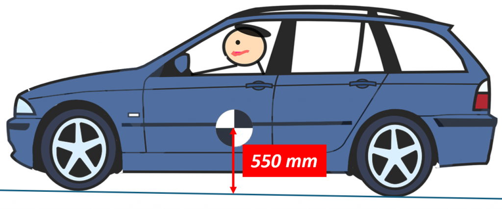
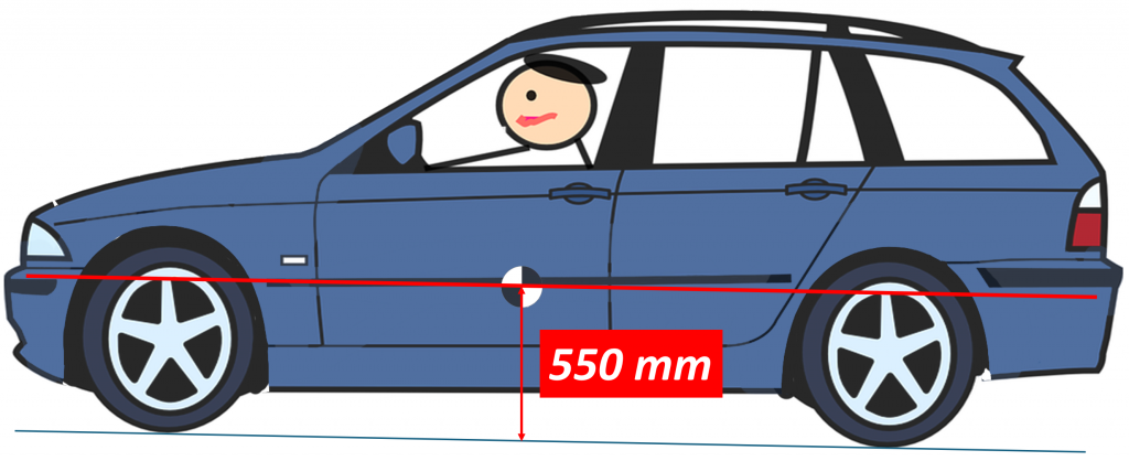
Here we see a typical car with a CG that is about 550 mm above the ground. But what would happen if the driver suddenly hits the brakes? The braking force would occur between the tires and the road and would look something like this:
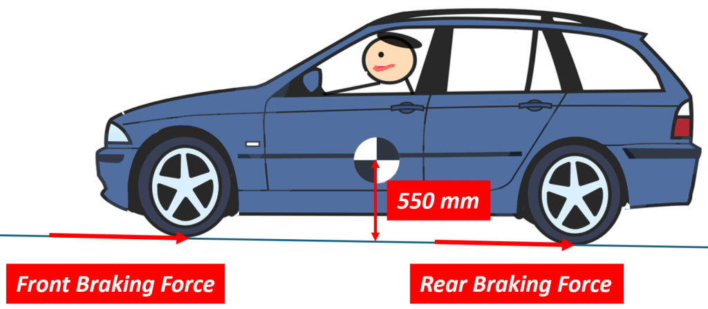
Both the front and the rear tires would generate some amount of braking force, and together they would act to slow the car down. But the car doesn’t actually want to slow down. We have Newton’s First Law of Motion to thank for that. It states that an object in motion wants to stay in motion unless acted on by some external force. This includes cars traveling down the road but also cars standing still. In either case, the car will not change its state of motion (whether already moving or standing still) until some force pushes on it. Of course, when you hit the brakes, you are creating just such a force, and this force pushes on the car at the tire contact patch. But since the car doesn’t “want” to slow down, it pushes back against this new force and the only place it can do that is at the CG since that is where the mass of the car is concentrated. This is called the inertia force, and it looks something like this:
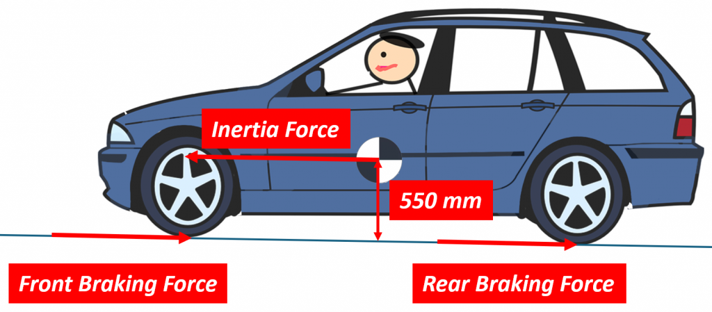
Notice that the braking forces and the inertia force are not in line with each other. There is a distance between them that is equal to the height of the CG above ground. This distance, together with the braking force creates a “moment” that wants to rotate the car. In the drawing above, it wants to rotate the car counterclockwise.
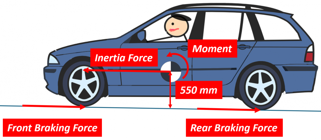
The only thing that keeps the car from actually rotating is the fact that it is sitting on its tires and the tires are against the ground. Imagine a rod sticking straight out of the door of the car and grabbing this rod with your hand. Try to rotate the car so that the front pushes down and the rear lifts up. If the front and rear tires are far apart, i.e. the wheelbase is long, it is clear they would have an easier time resisting the rotation of your hand. If the front and rear wheels are instead close together, you will have an easier time rotating the car and it might even be possible for the moment created by your hand to lift the rear wheels off the ground. You see this with bicycles and motorcycles. The wheelbases of these vehicles are small enough that heavy braking can cause the rear wheels to lift off the ground.
The force we are talking about here, the one trying to push the front down and lift the rear, is called the weight transfer force and it is easily calculated like this:
Weight Transfer Force = Vehicle Mass x Deceleration x CG height / Wheelbase
Let’s say our little car weighs 1500 kg, and we are trying to stop at 0.5G. Let’s also assume the wheelbase of the car is 2800 mm. The weight transfer force would then be 1500 x 0.5 x 550 / 2800 = 147 N. This means the front end effectively gets 147 N heavier and the rear end gets 147 N lighter. All that extra “weight” in the front needs to be carried by the suspension and the springs, which is why the front end of a car goes down during braking. Similarly, the rear gets lighter, so the rear suspension and springs don’t have as much work to do, and the back of the car goes up.
You’ve probably noticed this in your own car when you hit the brakes. The front goes down and the rear comes up. The front and rear suspensions are simply reacting to the weight transfer force causing the front end to get heavier and the rear end to get lighter.
But what if there were a way we could use the braking forces to counteract the effect of this weight transfer? What if we could use braking force in the front suspension to push back up against the weight transfer force and the braking force in the rear suspension to pull down on the body during braking? If we could do this, we could reduce or even eliminate the pitching motion caused by braking. It just so happens that there is indeed a way of doing this and it’s called “anti-dive” and “anti-lift”.
Suspension “Anti” Properties
Back in March of ’23, I wrote a post on suspension roll centers, and if you’ve read it, you may remember that the higher the roll center was, the less the car body would roll in a corner. You may also remember that we figured out how high the roll center was by drawing a line from the tire contact patch to the instantaneous center of rotation of the suspension. The higher the angle of this line, the higher the roll center and the less the body would roll during cornering. You could think of this line as the “anti-roll” line of the suspension. We do something very similar when thinking about anti-dive and anti-lift but instead of looking at the car from the front or rear, we look at it from the side.
Let’s start with Anti-Dive
Anti-Dive
Anti-dive is a property of front suspensions, and it refers to the ability of the suspension to take the horizontal braking force happening at the tire contact patch and turn it into a vertical force that pushes up against the body, thereby negating some or all of the downward force caused by the weight transfer. Anti-dive is specified as a percentage where 100% anti-dive means that the suspension can turn enough of the braking force into a vertical force to counteract all of the weight transfer force and 0% would mean it turns none of the braking force into a vertical force. In the case of 100% anti-dive, the result would then be that the front suspension doesn’t move down at all under braking. All of the weight transfer force would be counteracted by the suspension and the body just stays where it is. Sounds kind of cool, but we’ll see later why this may not actually be a good thing.
So, how do we design a suspension that provides this mysterious anti-dive property? Or, how do we figure out how much anti-dive a particular suspension has? The answer is actually not that complicated and just like with roll centers,; here are two basic methods for figuring it out.
The first, I call the geometric method and it’s the one you will most likely find in textbooks and online. The second method I call the Instantaneous Radius Method and while it is the most accurate, it requires having a computer model of the suspension.
In both cases, we need to know if we are dealing with a live axle or independent suspension and if have inboard or outboard brakes. Since an independent suspension with inboard brakes is exceedingly rare, I’m going to ignore it here and focus on independent suspensions with outboard brakes. I’m also going to ignore live axles to simplify things. If anyone is particularly interested in the inboard brakes setup, we can communicate separately about it. I think it would just lead to too much confusion here. This stuff is confusing enough as it is.
Let’s start with the geometric method.
Geometric Method
In both the geometric and the instantaneous radius methods, what we are trying to do is determine the instantaneous center of rotation of the suspension as it moves up and down. Back when we looked at roll centers, we did this by looking at the vehicle from the front, but in the case of anti-dive, we need to look at the vehicle from the side. As the suspension moves up and down, it rarely just moves in a straight line. In most cases, it also rotates slightly. This rotation means that the suspension is effectively instantaneously moving along the edge of a circle of some size. We need to know how big this circle is and where its center is located. With the geometric method, we do this by drawing lines through the bushings of the suspension components. In the case of a double wishbone design, we draw a line through the two upper control arms bushings and another line through the two lower control arm bushings. Where these lines intersect is the instantaneous center of rotation of the suspension.
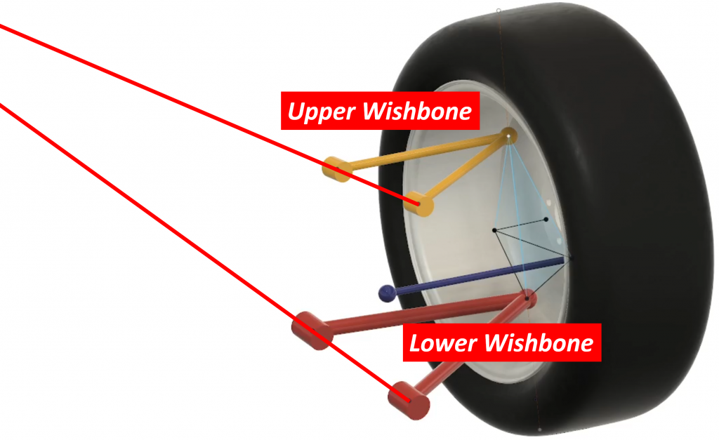
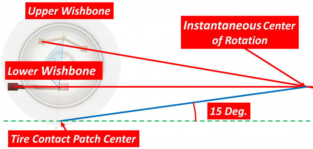
Let’s look at an example. Here is a model of a double wishbone suspension:
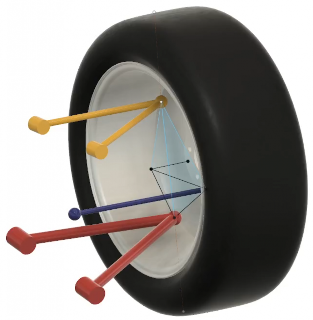
We can now draw lines through the upper and lower wishbone bushings:
If we look at this from the side…
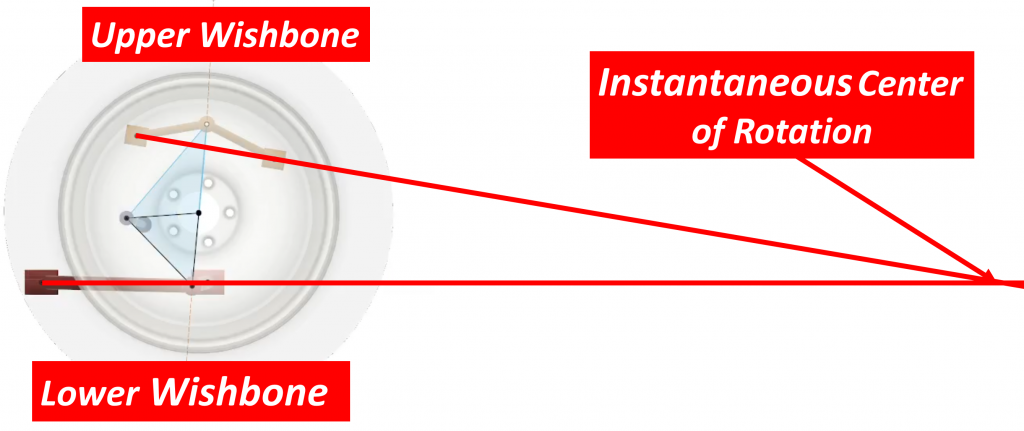
…we see that the lines intersect somewhere behind the wheel. That point is the instantaneous center of rotation of the suspension. We now draw a line from this point to the tire contact patch:
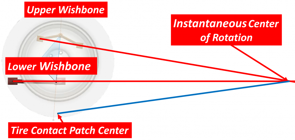
This line, shown in blue, represents the radius of the circle that the suspension is instantaneously rotating about. We now need to measure the angle of this line relative to the ground. Let’s assume that number is 15 degrees:
There are refinements we could do to this method such as projecting the lines along the plane of each control arm until they intersect with the wheel plane, but these will only make minor changes to the answer we got here.
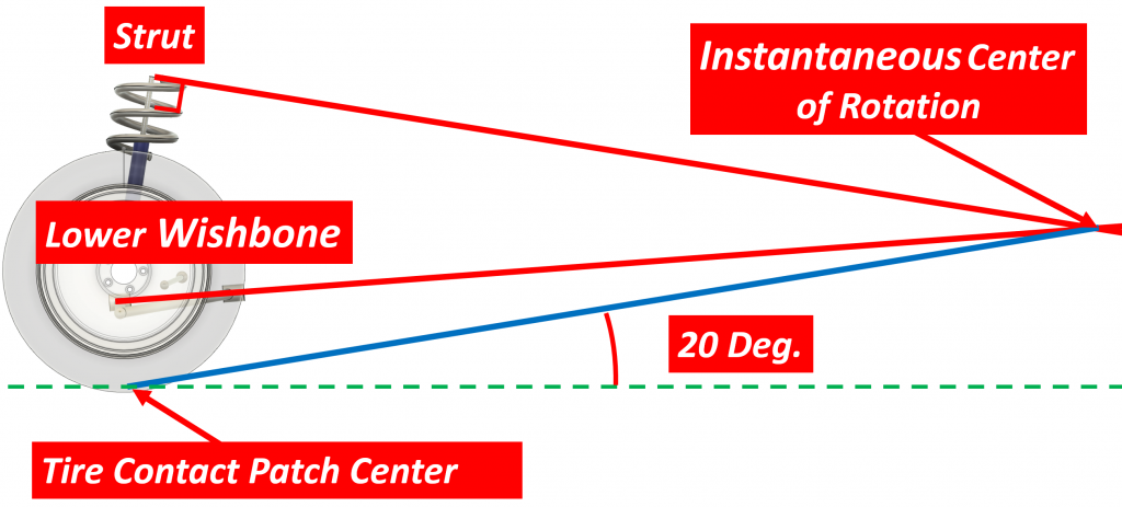
If we have a MacPherson strut suspension, the method is similar but since we don’t have an upper control arm, we instead draw a line at the top of the strut perpendicular to the axis of the damper:
With that, we are done with this part of the geometric method.
Now, let’s look at the instantaneous radius method.
Instantaneous Radius Method
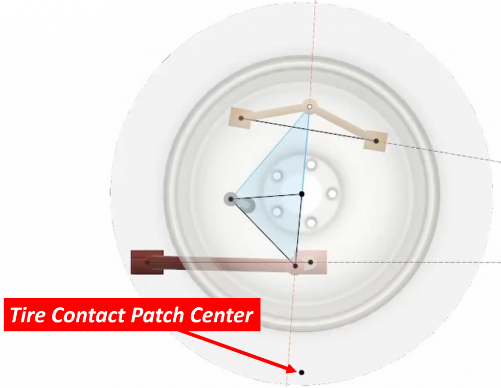
For this method, we will need a computer model of the suspension. And just like we did with roll centers, we will move the suspension up and down a small amount and see what happens to the tire contact patch. However, there is a critical aspect here which we didn’t have to worry about with roll centers. If we simply track the tire contact patch as the suspension moves up and down, we will get the wrong answer since the wheel and tire are able to rotate relative to the suspension. Instead, we need to imagine a point located at the tire contact patch but firmly attached to the suspension knuckle. Obviously, there is no part of the actual knuckle located at the contact patch, so we have to use our imagination. Fortunately, in the computer we can place points anywhere we want, even if they are physically impossible. Let’s use the double wishbone suspension as a model again.
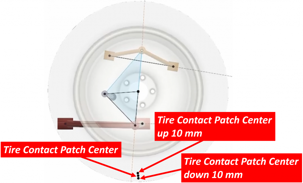
First, we look at where the contact patch is when the suspension is in its normal position:
We then move the suspension up 10 mm and record the location of this same point. Remember that this point follows the motion of the knuckle, NOT the motion of the tire:
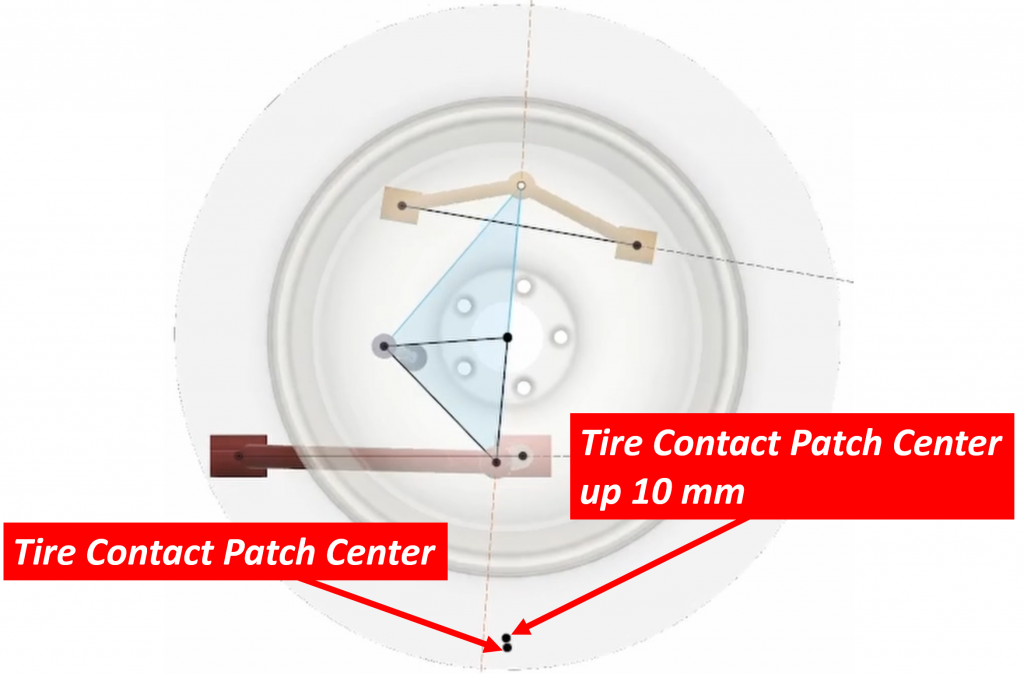
We then move the suspension down 10 mm and record the position of the point again:
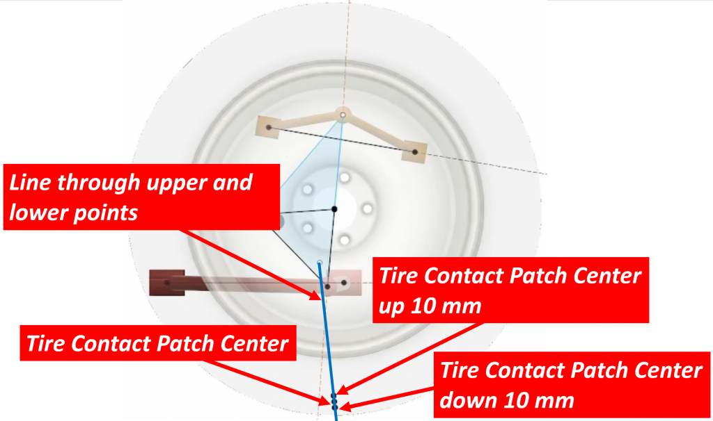
Once we have these three points, we draw a line through the upper and lower points:
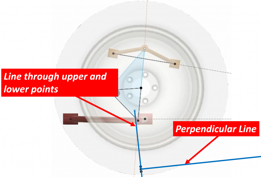
The last step is to draw a line perpendicular to this line at the original contact patch location:
What this tells us is that the center of rotation of the suspension lies somewhere along this line. The precise location of this point is actually not important since it is the angle of the line relative to ground we are interested in anyway:
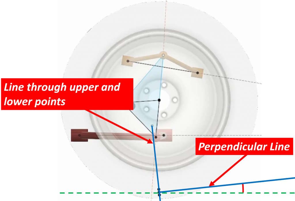
This method will give a much more accurate angle than the geometric method, especially as the suspensions get more complicated with multiple links, etc. In those cases, it is not clear at all which bushing you would use to draw the lines and the geometric method may not work at all.
The Ideal Line
As I mentioned earlier, anti-dive is described as a percentage. This means we are comparing two things relative to each other. We’ve shown two methods for determining the angle of the motion of the suspension, so we now need to determine what we want to compare this angle to in order to generate a percentage number. If we wanted our suspension to have 100% anti-dive, what would our angle need to be? How do we determine that?
To answer this question, we need to know a little more about our car. In particular, we need to know how much of the total braking is being done by the front brakes. This is also specified as a percentage and is a function of the design of the braking system. Normally, the front brakes do the majority of the work of stopping a car since the weight transfer we talked about earlier means the front is effectively “heavier” than the rear, so the front tires have more grip and are able to do more of the braking work. Brake engineers take advantage of this by making the front brakes bigger and more powerful than the rears. It’s called the “brake split”.
Once we know the brake split, we draw a horizontal line that passes through the center of gravity. We then draw a point that is behind the front wheels a distance equal to the wheelbase multiplied by the front brake split percentage. From this point we draw a line to the front tire contact patch and measure the angle of this line relative to ground. This is the “100%” line. If the angle of the line we determined for our suspension is the same as this 100% angle, then our suspension will have 100% anti-dive (i.e. the nose won’t move under braking). If the angle of our line is half of the 100% angle, then our suspension is said to have 50% anti-dive. If it is 1/3, then we have 33% anti-dive, etc.
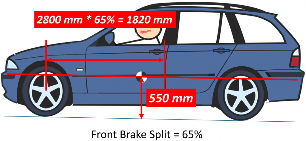
Let’s look at an example to make sense of this. Let’s take the same car we used before and assume our brake system does 65% of the braking work with the front brakes and 35% with the rears. In other words, our brake split is 65%. We start by drawing a horizontal line through the center of gravity:
Next, we measure a distance behind the front wheels equal to the wheelbase times the brake split. Remember that our wheelbase was 2800 mm:
From this point we draw a line to the front tire contact patch and measure the angle to ground:
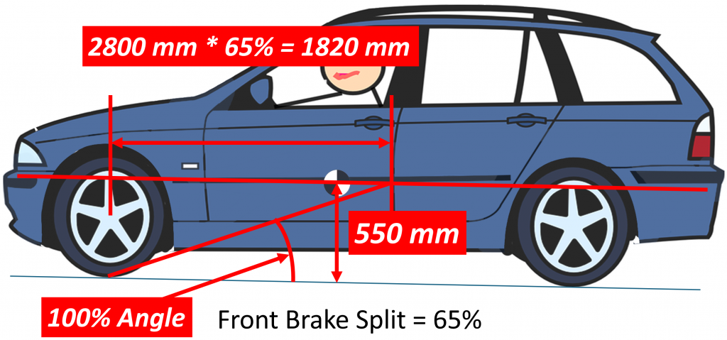
This is our 100% angle and it is the angle we compare our measured angle to.
Anti-Lift
In the rear suspension, the force that counteracts the effect of weight transfer during braking is called anti-lift and it does exactly what it implies: it resists the tendency of the rear of the car to lift under braking. The methods for determining anti-lift are exactly the same as for anti-dive except that we are now looking at the rear suspension instead of the front and instead of projecting the lines behind the suspension, we project them in front of it. Everything else is the same. We can use the same geometric method but since rear suspensions come in a much larger variety than fronts do, there are many instances where the geometric method simply doesn’t work. We MUST use the instantaneous Radius Method in those cases. It’s the only way to get the job done.
So What, Big Deal?
Why do we even care about all this? Why should we care how much the car pitches under braking? It’s still going to stop the same — having a lot of anti-lift or anti-dive isn’t going to make the car stop in a shorter distance.
All of these things are true. But what anti-dive and anti-lift can do for us is change the way we “perceive” how well the brakes are working and how well the car is stopping. This doesn’t sound like a big deal, but it actually is. When you hit the brakes in your car, you expect the car to start slowing down immediately. If you are in a car that has very low anti-lift and anti-dive, the car will pitch a lot after you hit the brakes. This pitching motion means that while the car starts to slow down, your head hasn’t yet. There is a small amount of time where the pitching motion means your head is still moving forward even though the car is in fact slowing down. This split second can be enough to give you a moment where you think the brakes are not working and it can cause you to step harder on the brake pedal unnecessarily. It all takes place in a very small amount of time, but it can be significant.
But it’s not just the pitching motion that is of concern here. It is also the direction of the pitch. Is your head pitching forward and up, is it moving straight forward, or is it going forward and down? Each of these will give you a different perception of how well the brakes are working.
Let’s look at some examples to see what I mean.
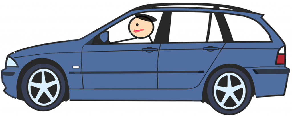
Here is our car under zero braking:
Let’s assume the car has a lot of anti-dive but very little if any anti-lift. In other words, a car where the front suspension doesn’t pitch down during braking but the rear pitches up a lot. Under braking, our car would look like this:

And the drivers head will have moved along a path that looks like this (notice the red path from the starting point to the driver’s eye’s final point):
Notice that the drivers head moved forward a little, but it moved up a lot. Imagine yourself in this car. You would have been thrown forward and up in your seat, as if you were being launched out of the car. Doesn’t sound like a very good feeling to me. Thrilling if you are on a fun fair ride, but not so good when you are in a car trying to avoid another driver who did something crazy.
Now let’s look at a situation where we have a car with very little anti-dive and also very little anti-lift. This car might look like this under braking:

and the drivers head would have moved like this:
It’s hard to tell even with this exaggerated image, but the driver’s head moved much less this time, and it moved straight forward, no upward movement. Seems like this would feel a lot better. You wouldn’t feel like you’re being thrown out of your seat.
But let’s look at one more configuration. This time with very little anti-dive in the front but a lot of anti-lift in the rear. Under braking, this car might look like this:
and the drivers head motion would be this:

Notice that the amount of movement of the driver’s head is a little more than the previous configuration but look at the direction. It has moved mostly down. From personal experience, I can tell you that this gives a very stable and confident feeling to the brakes. The car feels like it is being sucked down to the ground.
This is what I tried to achieve in all the suspension systems I’ve designed in my career. I never worried too much about putting anti-dive into the front suspensions, but I always put a lot of anti-lift in the rear. The results were cars that felt good under braking and gave the driver confidence in the car’s ability to stop when needed.
Top photo: VW. Blue clip art: Creazilla


Don’t EVs and hybrid cars with regenerative braking effectively have inboard brakes when using regenerative braking, and outboard brakes when using friction braking?
I had never given much thought to the brakes transferring vertical force except on swing arm suspensions where it’s sort of obvious.
Wouldn’t an easier way to to think of anti dive and squat be to determine the change in the distance between the wheels and the center of the car under braking if the front wheels move farther away from the center under braking, or if a weight is applied,, same thing, it’s anti dive. If the rear wheels move farther to the rear under weight , then it’s anti squat.
Upon further reflection, lengthening of the wheelbase would happen under increasing static load for anti dive and anti squat, but under acceleration and deceleration by tractive force (jet cars need not apply!) the forces to raise or lower the car should be in equilibrium.
By the same thinking, in a front wheel drive car, anti dive kinematics in the front suspension would be anti lift under acceleration, and the anti lift in the rear would be probably be unmeasurably small.
I have personal experience of how a car feels with zero anti-lift in the rear. A friend had a 1965 HD Holden Station Sedan (wagon) that had air shocks fitted to the rear. One day while hooning around with too much air in the shocks on a rough road, we broke one of the lower shock mounts and had to remove the air shock from that side so it didn’t clank around under the car, then found the handling was very weird with a shock on one side only, so took out the other one as well.
We soon found that under heavy braking, the rear of the car lifted substantially, and would easily lock the rear wheels as so much weight was transferred away from them. But then we discovered that if you braked heavily to lift the rear, released the brakes once the rear lifted fully, then stamped on them again once the suspension rebounded to full compression, the energy in the compressed leaf springs combined with the weight transfer lifted the rear even more. With a bit of experimentation, we found that pumping the brakes repeatedly in exactly the right way could lift the rear end so far that the front bumper would scrape on the ground! Being idiots in our mid 20s, we proceeded to spend an entertaining evening driving around performing this stunt at every red light we came to, much to the entertainment of the other road users!
No discussion of vehicles doing stoppies can exist without mention of this little gem. https://www.youtube.com/watch?v=HrhCAiV7diY
Note this is a GM sales film and the Econoline has been “specially prepared” for the tests. Clearly visible in many of the shots is the tail gate. The factory tailgate is the same height as the sides of the truck, this one is from a regular pickup which is shorter and lighter, moving CoG forward. In some of the shots thanks to that shorter tailgate you can see the bracket that holds the standard spare tire at the back of the bed on the driver’s side. Taking out the spare also moved the CoG forward. When they do the stoppie you’ll notice that there is a passenger in the truck and he is sitting on the dash/pressed up against the windshield, also moving the CoG forward and up. Based on the ride height and how the suspension is basically topped out when they do the lifting demonstration I also suspect they removed the large ballast plate that was installed from the factory and of course were running on almost empty all in the name of moving that CG forward and/or up in the name of a great shot and deceptive marketing.
My favorite demonstration of the friction circle and weight transfer visually demonstrated
https://youtu.be/x4qRVfioR2g?si=RkrcqwYrEU_-W5gO
That is good for sure.
Surprisingly no mention of was made of the door opening under braking.
Yeah that is kind of crazy that they point that out.
Love these articles, thank you! I love when cars seem to squat evenly upon braking. It almost feels like there’s something magical going on, especially when you grew up with cars that would prefer to stand on their noses.
Human sensory perceptions play a tremendous role in how we drive. In traffic engineering, there is the concept of the “shy line offset”, which is the (speed-dependent) distance away from the edge of the roadway that an object must be to avoid being perceived as a hazard. Humans tend to slow down when they feel too close to an object or cannot see over it. Ever notice how uncomfortable it feels to drive down a roadway with tall buildings, walls or trees close to the edge of the road? It’s the same reaction as turning down the radio to read street signs.
My tadpole trike likes to “dive” during hard braking, since I’m most of the mass, and my center of gravity is only barely behind the front axle line, and the front wheels are my primary source of traction during baking. More than once, the rear wheel lifted off the ground, which being RWD, can get quite scary because lateral stability is lost.
But damn can that SoB corner.
I get that physics engineering is a big part of car design, but articles like this make me realize how hard this all is. Maybe, if this is your job, and your mental gift, it’s great. And if not, like me, this is interesting until my mind goes, “I don’t have the ability to go there.” I’ll try again in a few days.
That is fascinating how it’s not actually about changing the abilities of the car but just our perception of the abilities of the car….wild.
I think that is also whey some early ABS systems were less successful than they ought to have been in stopping collisions – the sudden pulsing in pedal feel that more modern systems have managed to eliminate would cause some people to lift off the brakes in fright, rather than keeping their foot pressing hard for maximum braking.
Oh that’s a really good observation.
Yeah releasing the brake wasn’t uncommon. I know that many police officers complained about early ABS systems and claim that it caused them to crash.
I seriously love these nerdy deep-dives on suspension fundamentals. I don’t know what I’ll ever use the knowledge for, but I really like having it.
Trust me. This stuff works fantastic in a bar!
COG is why BEVs can often “feel” like lighter cars. The way we are accustomed to experiencing dynamic forces in one way, and BEVs subvert those expectations. A massive battery close to the ground might even be able to cause the car to almost lean “in” to turns. Unfortunately for BEVs, that weight also requires vast amounts of mechanical grip to get it to shift directions. All that grip requires more dampening, mechanical assistance, and tends to reduce road feel.
I found your video on anti-squat and the concept of the wheel moving in a slot very helpful in understanding how the suspension actually generates the forces to pull the body up or down for anti-lift and anti-dive.
One thing I would like to understand better is how a live axle changes this. At minimum, I assume a live axle has stiffer springs to manage the unsprung mass, so at minimum you would have less deflection for a given amount of weight transfer. But I did not really understand the part about reaction forces in the differential.
Live axles do not have stiffer springs because the springs primarily control the motion of the body, not the suspension. It’s the reason why ride over rough roads with a live axle is so much worse than an independent suspension. The springs simply can’t control all that mass moving around.
As far as your question about reaction forces goes, this is probably the hardest to understand part of this whole thing and the part many people get wrong. What you need to do is look at all the forces acting on the knuckle when you accelerate. Engineers do this by drawing what is called a “free body diagram”. In an independent suspension, the halfshafts go through the knuckle via the main wheel bearing. Since bearings can spin, they cannot transmit a torque or moment, only a force. This means that the halfshafts can only apply a force onto the knuckle and that force will be located at the center of the shaft. As far as the knuckle is concerned, the only force that exists when you accelerate is a force pushing it forward. There is no twisting going on. With a live axle, the knuckle is rigidly connected to the knuckle since they are both part of the axle housing. This means that the knuckle also sees the torque generated by the differential. The “knuckle” sees both the forward force pushing the vehicle forward and also the torque generated by the differential and the rest of the powertrain. This is why live axles “wind-up” under acceleration. They twist in the opposite direction from the tires. This lifts the nose of the differential and under really heavy acceleration, like in a dragrace car, it can sometimes even cause the differential to hit the underside of the body.
Thanks! I took a look at your article on axle hop and this helped. I suppose in that case it’s the combination of the reaction torque on the axle housing and the leaf springs that allow this motion. Either an independent suspension to
eliminate this torque or a live axle with upper and lower trailing links to resist the axle torque more effectively.
It doesn’t matter how the axle is attached. Leaf springs make the problem more obvious but even with 4 links, the torque is still there. It just doesn’t wind the axle up as much because the bushings in the links are stiffer than a leaf spring.
I’ve noticed that RWD cars w/ independent rear suspension can have wheel hop on hard acceleration.
Having had an XM and a CX, the peculiar feeling of the rear squatting when braking is one of the characteristics i really miss and haven’t yet experienced to such a degree in any other car. The fact such a softly sprung car has basically no dive under braking I found so cool and counter-intuitive, keeping in mind the potential for dramatic body motions in any other situation with that car.
https://youtu.be/cMGCKMWJUWE?t=763
My late father’s best friend leased Citroën for thirty years, going from DS, CX, to XM. Growing up with his DS and CX was memorable as he loved showing off Citroën’s unique features with hydropneumatic suspension system, pivoting driving lamps on his DS, squatting rear end during hard brake, etc. When I rode his CX for the first time, I spent so much time staring at the instrument cluster and control pods that I forgot about everything else. For a kid, CX was most futuristic and science-fiction thing ever.
That video brought back lot of memories.
Why is it that once I start watching Hubert’s suspension explainer videos I always have to watch them all the way through? Great job explaining these complex concepts!
Thank you, sir. And thanks for watching all the way through. Keeps my stats up 🙂
Huibert, you do an amazing job explaining something so complex, in a very non-intimidating way that fosters intrigue to better understand! I had to read the article more times than I care to talk about but, that is only because you make me want to really understand and be able to apply or share the new-to-me knowledge. Hats off sir!
Thank you and you are most welcome. I have the good fortunate to have had some very good mentors in my career. I can only hope to be as good as they were.
I love this kind of content, I learn so much!
Huibert, any chance of a deep dive into the 2CV suspension? I believe Torch can help with this…
Yes, I know Torch has one and I would love to do a deep dive into it. We don’t live very close to each other, unfortunately. Still, it is something I hope to remedy some day.
The [center of mass] knows where it is at all times. It knows this because it knows where it isn’t. By subtracting where it is from where it isn’t, or where it isn’t from where it is (whichever is greater), it obtains a difference, or deviation.
You should never deviate from your center of mass. That would be a bad thing!
Does building in more anti-dive damage ride quality since now, the front wheels have to move forward while going over bumps? Seems like it would require softer springs to deal with that geometry and still absorb bumps?
No. The behavior of the wheels over bumps has to do with what the center of the wheel is doing, not the contact patch. With a double wishbone, it is quite easy to make the wheel center move up and rearward while still making the contact patch move up and forward. It’s a little more difficult with struts, but not impossible.
Difficult to picture, but I’ll try! Are there any downsides to building in anti-dive and -lift? If not why don’t all vehicles brake like the M5 in the video someone else linked?
Building in tons of anti-lift into the rear suspension is not easy and can compromise other things. BMW used a semi-trailing arm in the early 5 series but that suspension has other issues which they solved with the integral link they replaced it with. This new design had much less anti-lift but it was still enough and it fixed other issues they had. It was a good compromise, in my opinion.
Watch Motorweek retro reviews and look for old BMWs (E34, E39). They brake flat. I don’t know how they did it at a time where tech wasn’t there yet, it must have been pure engineering prowess. Keeping some weight over the rear tires definitely helps brake better because you can keep more pressure on the brakes before they lock up, or so I always thought. Those braking distances were records for road cars for the time.
https://youtu.be/r4PMkQLT3rE?t=171
You can see how the whole car squats instead of diving. It’s incredible.
That’s… that’s frickin’ beautiful.
BMW’s have always been very good at putting lots of anti-lift in their rear suspensions. In fact. the early 5 series had over 100% anti lift. The rear would actually go DOWN under braking!
Also, it’s not about tech. This is just good fundamental suspension design.
Oh god “weight transfer” is just a tad below “high rate of speed” in my all time trigger list.