
The challenge with assembling a brand new WWII Jeep is that I not only have to purchase every single component for an entire vehicle, but those components have to be minty fresh. I can’t use a raggedy old steering system from a used WWII Jeep; I have to build a brand new one. Here’s what that was like.
As I look into my backyard and see a frame sitting on a suspension, I remind myself of the critical systems I have to pay special attention to: brakes, steering, engine lubrication, and engine cooling. Those are the ones that, if screwed up, lead to very bad things.
Prior to installing the brand new engine my friend Laurence and I were finishing up, I wanted to have the steering system in place, as the engine makes doing it afterwards a bit tricky due to space constraints. Here’s a look at part of the WWII Jeep’s steering system:

Mounted on the frame is a steering box, labeled #12 in the diagram above. That steering box features a sector shaft (#7), which has splines at its end that the pitman arm (#5) slides onto. When you turn the steering wheel (#1), it rotates a steering shaft inside a steering tube/column (#4 sort of points to both).
You can see at the bottom of that steering shaft is a worm gear with bearings (#9) at both ends. That worm gear goes into the steering box and mates with the sector shaft. So as you steer the wheel, it rotates the worm gear, which rotates the sector shaft, which swings the pitman arm in an arc.

At the end of that pitman arm is a drag link (#5, called a steering connecting rod in the image above). Turning the steering wheel pushes and pulls that drag link forward and backwards, pulling on the steering bellcrank attached to the axle. This bellcrank rotates, pushing and pulling a pair of tie rods (#11 and #24). The rotating bellcrank moves the tie rods together, either left or right. The tie rods exert a force on the front of the steering knuckles, which rotate about their kingpins, ultimately steering the wheels.
As you can see, there are lots of moving parts here, and I intended to replace every single one of them with a brand new component from eBay.
Building Up The Steering Column And Steering Box
I managed to snag a steering box housing off eBay. This isn’t a wear part, so I was OK with it being used; it showed up in mint condition:

That box doesn’t come with a lid, so I had to buy one of those. This one was a new-old stock dated 1959:


I also bought an entire steering box rebuild kit, which comes with new brass bushings for the sector shaft to ride on and new ball bearings for the steering shaft worm gear:

Speaking of the sector shaft, I bought a brand new one for $80: 
And for the end of that sector shaft I snagged this brand new pitman arm:

As for the steering column that goes into/onto the steering box, I bought a new shaft and tube from a seller in India: 
I wasn’t so sure about that tube that came with the shaft, so I snagged a beautiful New Old Stock one from Nelson’s Surplus Jeep Parts out of Columbiana, Ohio:

I also got a great deal on a new steering wheel:

And I had to purchase a bunch of smaller parts for that column, like the horn button/wire that goes through the column, the upper column bearing, a better clamp than the one that came with that India-sourced tube and more:


Putting it all together was a cinch, and I have to thank everyone in the WWII Jeep community who put together YouTube videos and especially the old-timers who did write-ups. There’s a website called 1944mb.com, and there’s a 1943mb.com and there are even GPW websites; I’m not sure who runs them all, but they feature incredible write-ups like the one hyperlinked there.
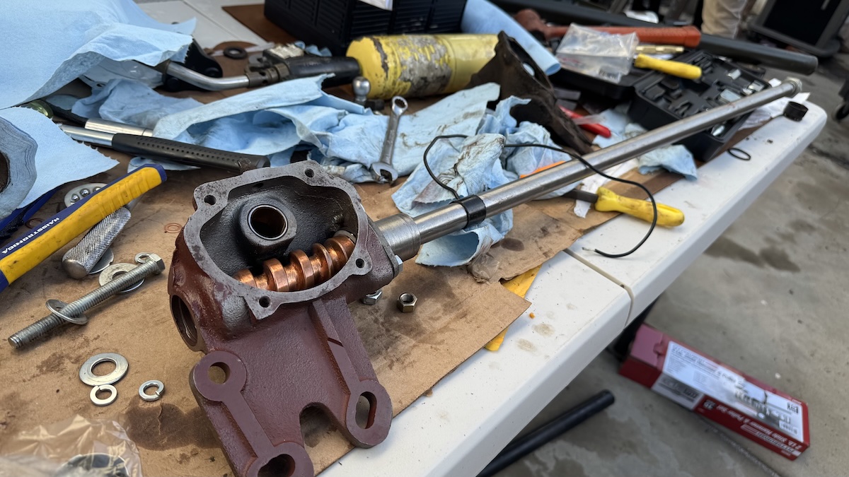
Rebuilding a WWII Jeep steering box is actually a lot of fun. You just load up some ball bearings on either side of the steering shaft worm gear (they’re held against a race with a little clip), and you press in a pair of bushings into the steering box, along with a seal on the back side. Here’s that steering shaft inserted in the steering box, which has new bushings pressed in:
Here’s a closer look at the bearings on either side of the shaft’s worm gear, and those two bushings; there’s a gap between the bushings in that bore because otherwise they’d block the oil fill hole for the steering box: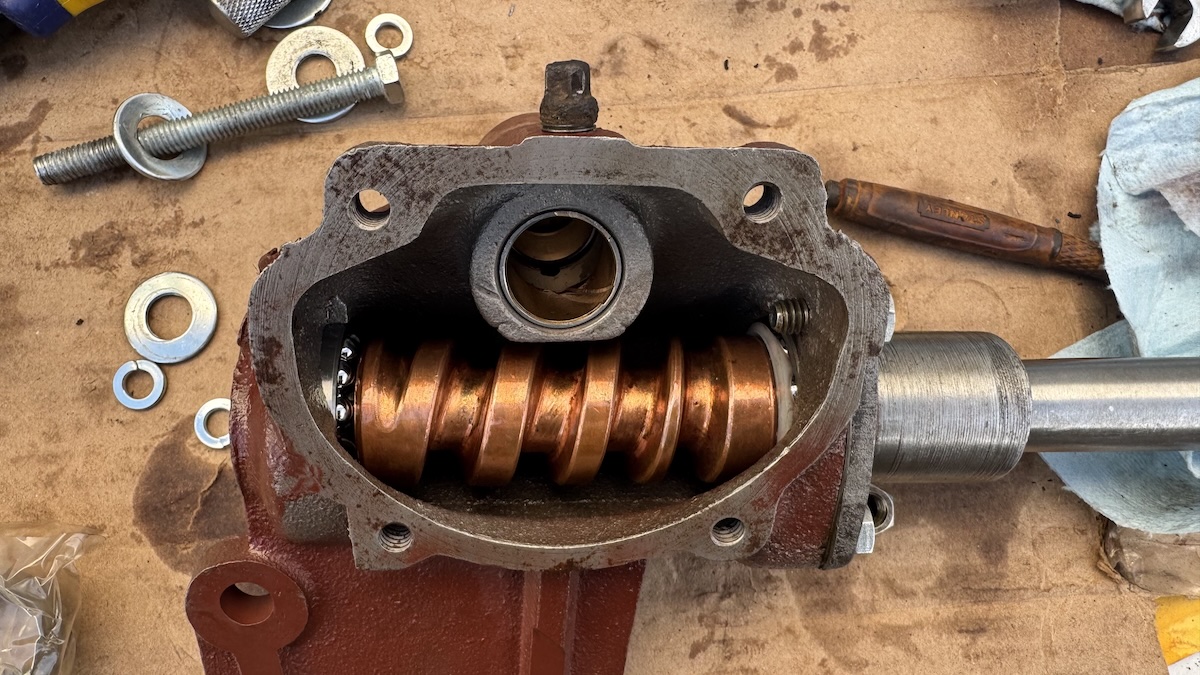
Then I slid in the sector shaft such that its fingers were riding on the worm gear and its round shaft was riding on the bushings:
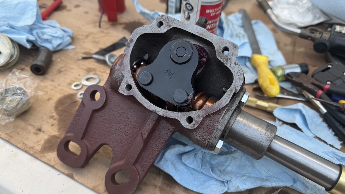
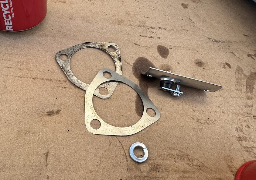
Notice there on the right, there’s a cast bearing retainer being held to the steering box via three bolts. That bearing retainer is squishing some thin shims — basically, paper-thin pieces of metal like this:
As with any bearing, it’s important they have the right pre-load (i.e. they’re being pushed against their races a bit). What I did was stack just the right number of shims between that bearing retainer and the housing such that I was squishing the worm gear (and its two bearings) just enough that there was no end-play in the steering shaft (in other words, I couldn’t move it axially).
View this post on Instagram
The steering box was pretty much done at that point. I did have to send a horn wire down the steering tube through this hole:

Just ahead of that hole I had to press a brass bushing onto the shaft (with a plastic insulator between the two), and I tried soldering the wire to the ring, but I just gave up and used tape.
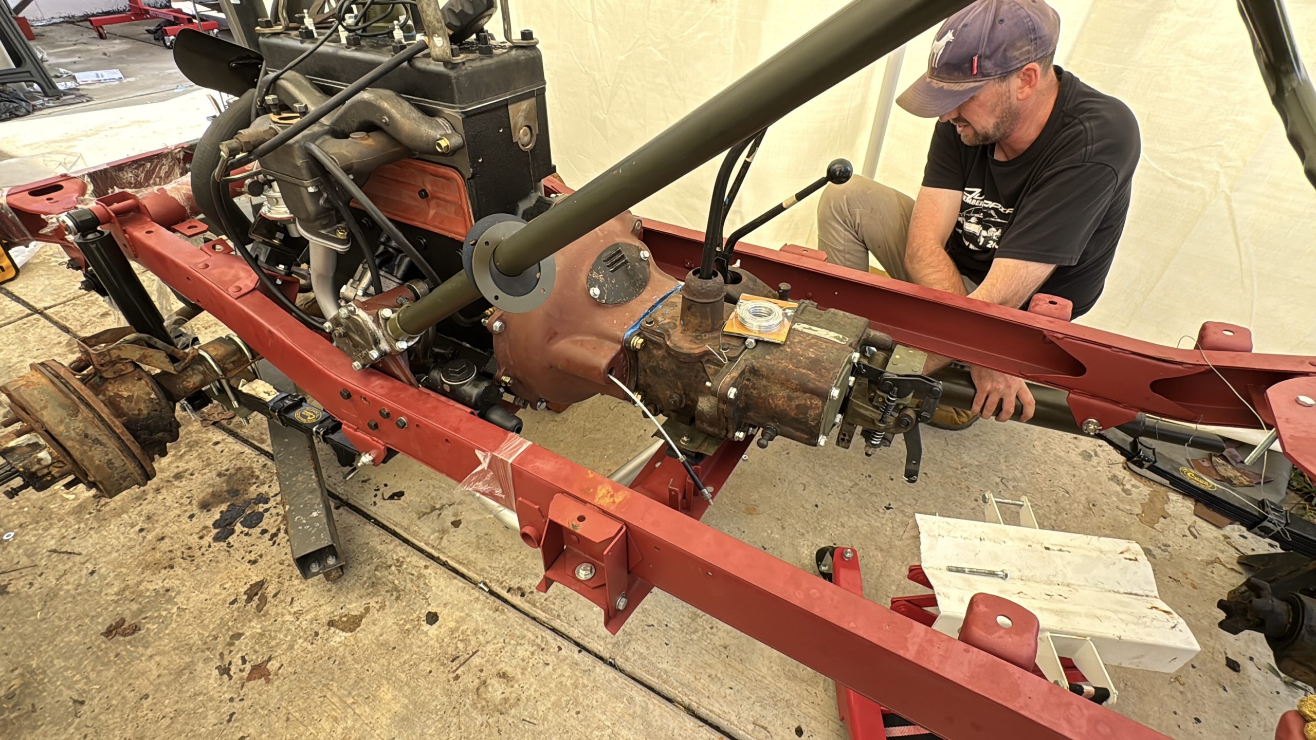
Here’s Laurence and me installing the steering column over the shaft:

And here you can see the horn ring and wire:
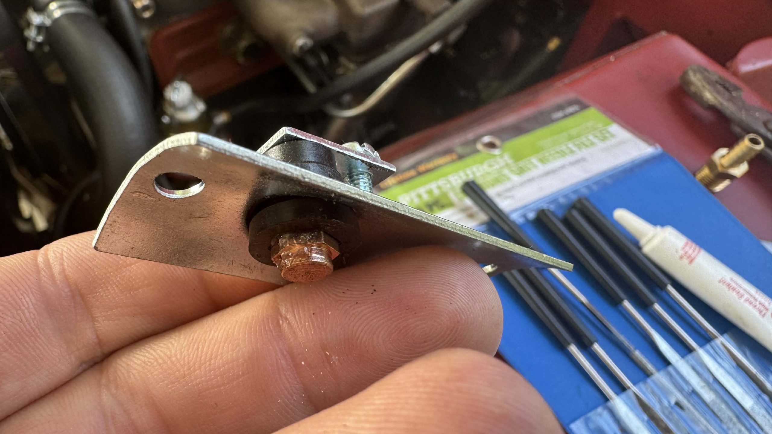
This little follower (we’ll call it) bolts up to the steering column tube and rides along the ring, triggering the horn when the button at the top of the steering shaft is pressed:
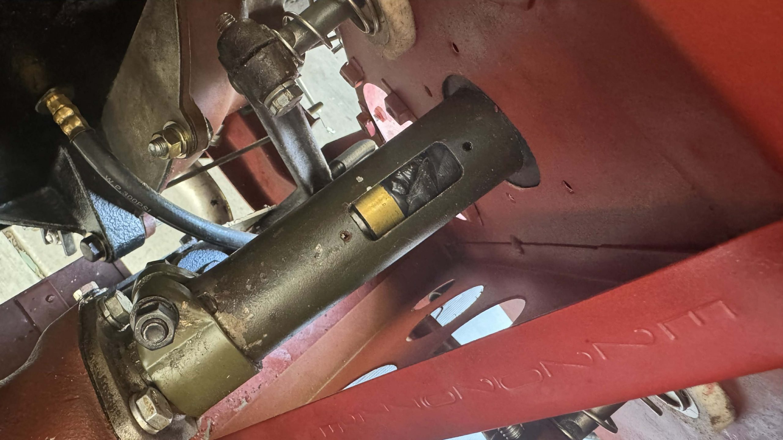
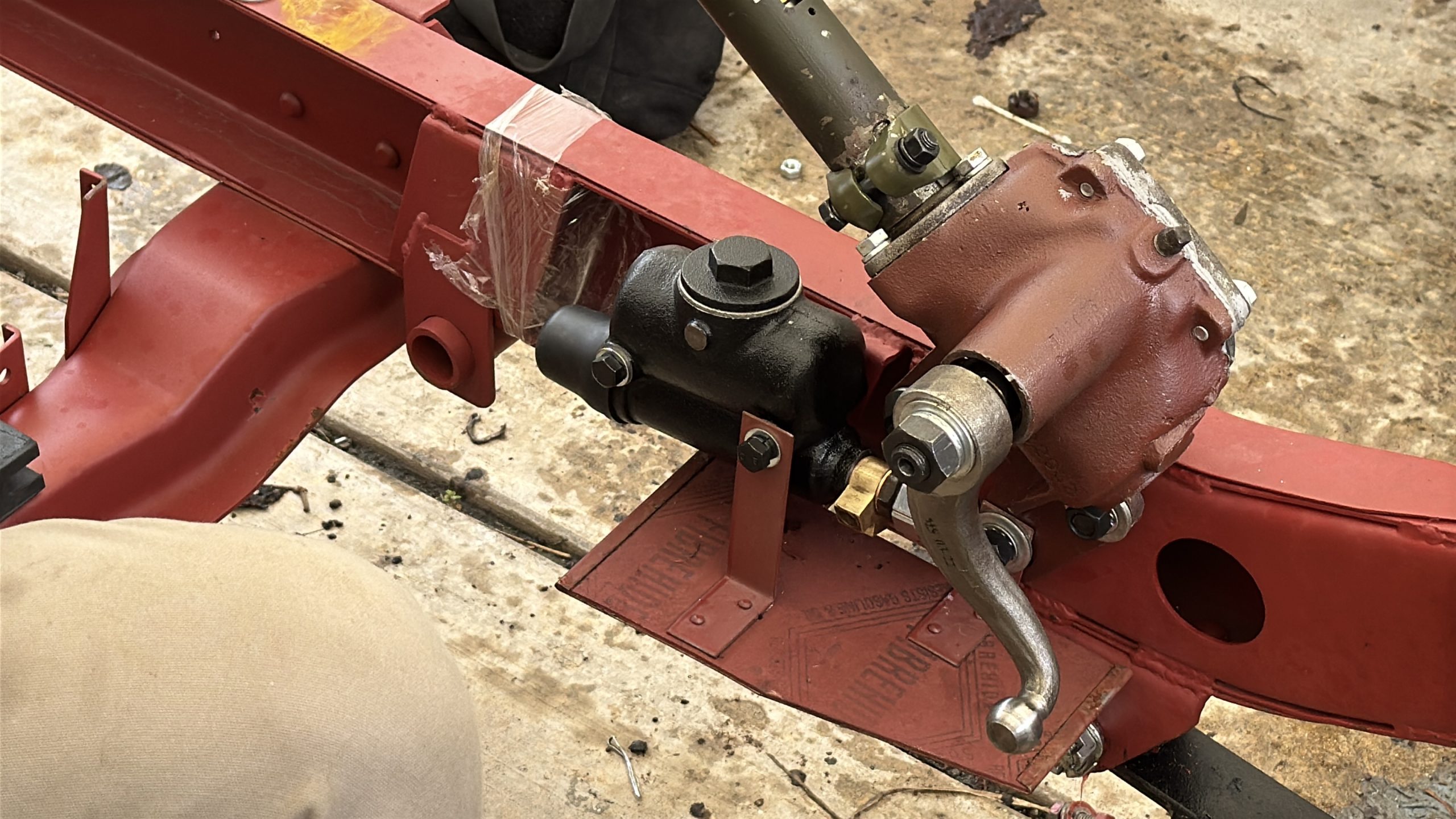
Here’s the steering box and column all mounted up to the frame:
The part that connects to the steering box’s output pitman arm is the drag link. It’s basically just a big rod with some ball joints at each end.
I snagged a used one for $55:

To rebuild the joints, I simply bought a drag link rebuild kit from eBay:

Basically, I’m just replacing the innards of a ball joint. There are threaded plugs at the ends of the drag link that work with the springs shown above to squeeze the cups (also shown above) against the ball on the pitman arm and bellcrank. That’s really all there is to it — just springs, cups, and plugs:
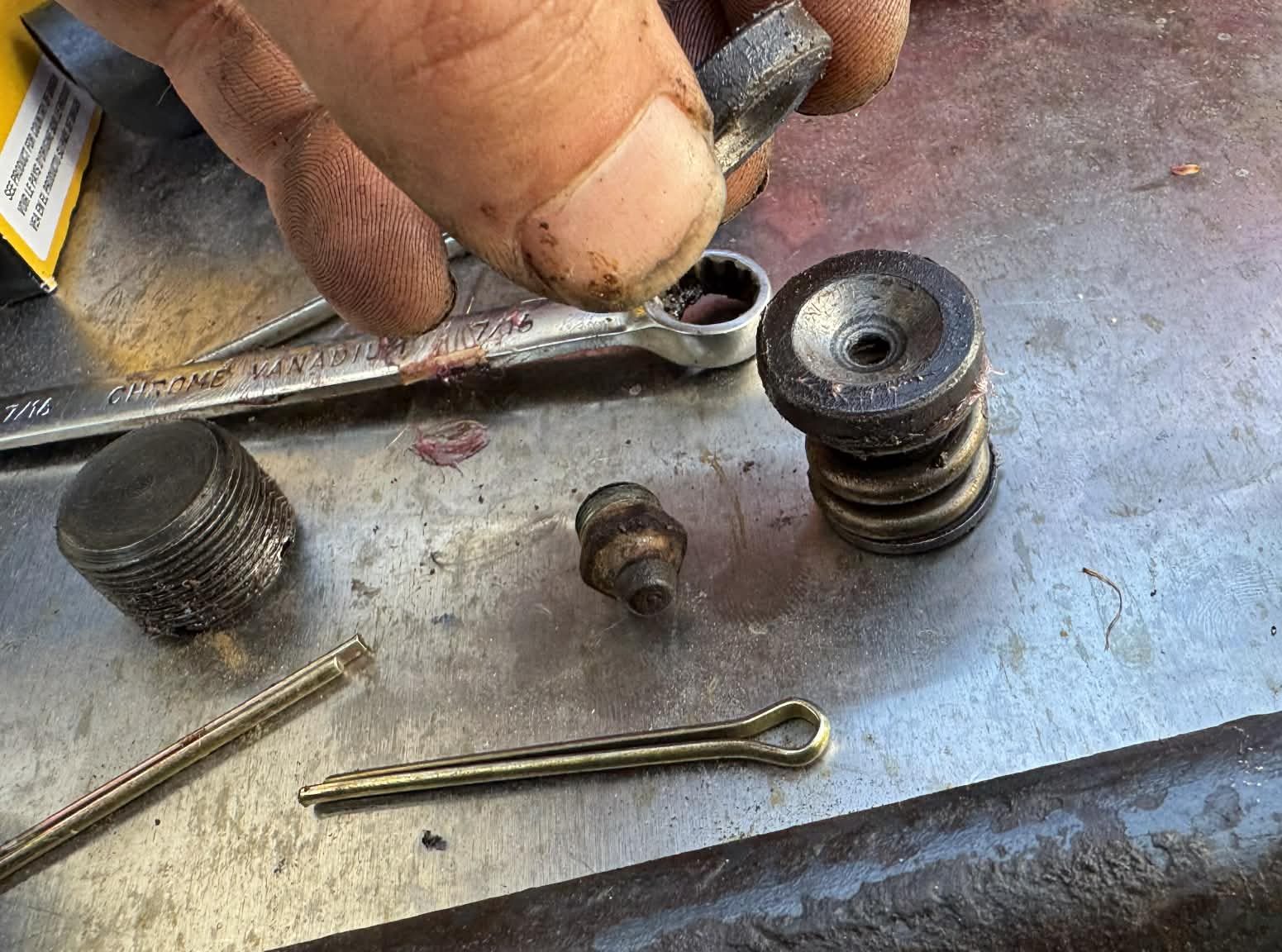
Here’s a look at the diagram of a similar drag link:
The other end of that drag link hooks up to a bellcrank. We rebuilt that as well using this repair kit from QTM Jeep Parts:

That basically just involved pressing in some new bearings and seals:
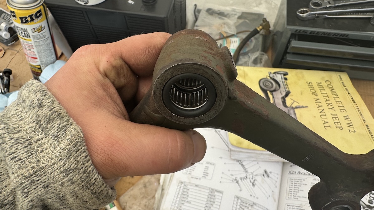
We’d like to have replaced the shaft itself in the axle, but that thing was not budging, and it appeared in good shape, allowing for smooth bellcrank operation:

Attached to the bellcrank are the tie rods, which came with the axles I’d purchased from an eBay seller in Washington.
Those tie rods had threaded ends that did not want to budge, but with the help of a local driveshaft shop whom I paid with a case of beer, they were broken loose, and I replaced them:

The last part of the steering system is the kingpins. These are basically like ball joints on a more modern car in that they set the axis about which the wheel steers. There’s an upper and a lower, and they’re basically just tapered roller bearings:

The end of the axle is ball-shaped and features two holes that receive bearing races. You can see one on the right in the eBay listing photo below. I hammered out the old races, pressed in new ones, and then packed the tapered roller bearings with grease. Then I inserted the bearings against the races while installing the knuckle.

As you can see in the diagram below, there are bearing caps (#12, that — when tightened against the knuckle (#9) — push the tapered roller bearings up against the bearing races in the end of the axle (not labeled, but the end of the axle is between the two sets of bearings and races (#18 and #19)).
As I mentioned before when discussing the steering shaft bearings, preload is very important, and you set the kingpin bearing preload by using shims (#11) between the bearing caps (#12) and the knuckle (#9). It took me forever to find bearings; I had to order some all the way from Great Britain:

I kept installing various shim stacks between the bearing caps and knuckle until they squeezed those kingpin bearings up against those bearing races in the axle just right.

Actually, “just right” is quantitatively defined. On a WWII Jeep, you want about 12 pounds of force before the knuckle begins to rotate, and you can measure this like I did above using a pull-scale hooked to the knuckle’s steering arm.
I got my kingpins to exactly 12 pounds, and I knew my shim stack was perfect, so I buttoned it all up.
So there you have it — a complete steering system, fully rebuilt. A rebuilt steering box, a new steering shaft, a rebuilt drag link, a rebuilt bell crank, rebuilt tie rods, rebuilt kingpins, and on and on. It’s all brand new and moving smoothly.
I’m taking as few shortcuts as I can because I want this Jeep to be mechanically perfect. What will be interesting is seeing how all these brand-new parts and systems work together for the very first time. Moab’s Easter Jeep Safari is in [checks watch], a week (as of this writing)! So hopefully we’re going to find out soon!
[Ed note: David mentioned the idea of building a brand new WWII Jeep to the team at eBay, and they loved the idea so much they said, “How can we help?” Their financial support and David’s Jeep obsession are the fuel behind this crazy build. – MH]


A few years ago I recall reading that Omix sector shafts were prone to failure. They would separate under load and render steering inoperably. A number of other repro parts have failed regularly as well. I haven’t installed any safety critical repro parts on my MB or M38, but it’s clear some of the reproductions are not of the same quality as original. David, how are you screening to ensure your repro parts aren’t the failure prone versions, especially the critical components?
What is the worm gear made of? Looks like copper/brass.
I spy some Hairball Fright tools.
They made a crap ton of these Ross style steering boxes, but there is a glaring flaw- the sector shaft is only supported by a bearing on one side. It’s floating on the other side. I’m surprised the aftermarket has not seen fit to put a bearing in the box cover and make a longer sector shaft that can ride on two bearings instead of just one.
So David Tracy does build his modern WWII Jeep just like the rest of us mortals: one ball bearing at a time.
It’s all ball bearings nowadays.
It’s all a bunch of balls.
Oh gosh, so astonishingly complex for an ostensibly simple vehicle such as a WWII Jeep… kudos to you, Laurence, case-of-beer-compensated mechanics, et al.!!
Yeah, it’ll be interesting to see the total cost but I daresay it’d actually be more interesting to see just how many individual parts and pieces you all had to put together. Were you able to keep track of the count or would it have been a bit too overwhelming?
If you kept track of the count, you could have a contest, à la the carnival jar of jelly beans, to see who can guess the nearest to correct number with the prize being a ride in the Jeep or something like that.
Nice job!
Follow the directions, and it turns out right. And, one hopes, turns out left as well.
Does the horn sound like a Plymouth Road Runner horn?
“cinch”, my man.
Ah, the universal currency! 🙂
When the final post comes on this project, I hope we see a cost for the BOM. I’m curious what the cost is to build one of these.
Yeah, the reality of a ground-up build would be very interesting. I’m going to say right now that this is one of the most expensive WWII jeeps in existence, even before adding labour costs.
I’m curious about parts numbers and compatibility among different manufacturers, NOS vs reproduction, etc.
During WWII, there was shitload of standardization of parts between manufacturers of components. Those standard would evolve into the MILSPECs we have today.
This isn’t all that different from the steering box on my ’69 Alfa. Do you worry about caster/camber/alignment?
The complexity of even this 85 year old design make me impressed with how hard car manufacturing really is.
What blows my mind is that some of these old processes that required all this finicky adjustment and complex assembly have actually been eliminated by modern technology and more advanced mass-manufacturing. Either we’ve found ways to dial in the tolerances in the manufacturing of the part to what they need to be without adjustment or we’ve found a way to loosen up the tolerance so it’s easier to go together while still maintaining function.
It’s sad because while a lot of the newer stuff really is better and will last much longer while performing far better, it doesn’t have that air of craftmanship where a guy was manually setting shim stacks to get everything just right.
And then to think that all that was being done with by-hand calculations and hand-drawn engineering drawings.
Modern stuff isn’t always more complex!
A disc brake is way simpler than a drum brake. A rack ‘n pinion is way simpler than a steering box system.
The steering system for this Jeep is almost identical in design to the steering using in today’s commercial vehicles. The pre-trip inspection script for passing a CDL exam was running in my head as I read this article and viewed the diagrams.
Depends on the application for disc brakes. Once you get into Class 5 and above trucks, the rotors are mounted inboard of the hub, and the calipers are quite the piece of kit to operate with air brakes.
Compared to air drum brakes, which have about 12 parts in total, and a complete 4 corner brake job can be done in under an hour.