")
Dear Autopians. It’s time. It’s time to go deep. Deep into the depths of engineering nerdom. Do you want to know the physics behind how bolts work (they work essentially like springs)? Do you wonder how automakers decide which bolt size to use? Are you curious how they come up with fastener installation torque specs? Do you wonder how much of that force you put on a ratchet actually goes into creating a clamp load versus how much is just overcoming thread friction? These are the things you will learn as we go down a path that many have tried and failed to travel. So grab the hand of the person next to you — it’s dark down there — and follow me as I guide you into the wonderful, fascinating world of the most ubiquitous and much maligned component in all of engineering: the fastener — a component more complex and interesting than most people give it credit for. Yes folks, it’s time to learn about the lowly nut and bolt.
[Welcome to Huibert Mees’s column, where the former Ford GT/Tesla Model S suspension engineer gets to write whatever he wants on The Autopian. -DT]
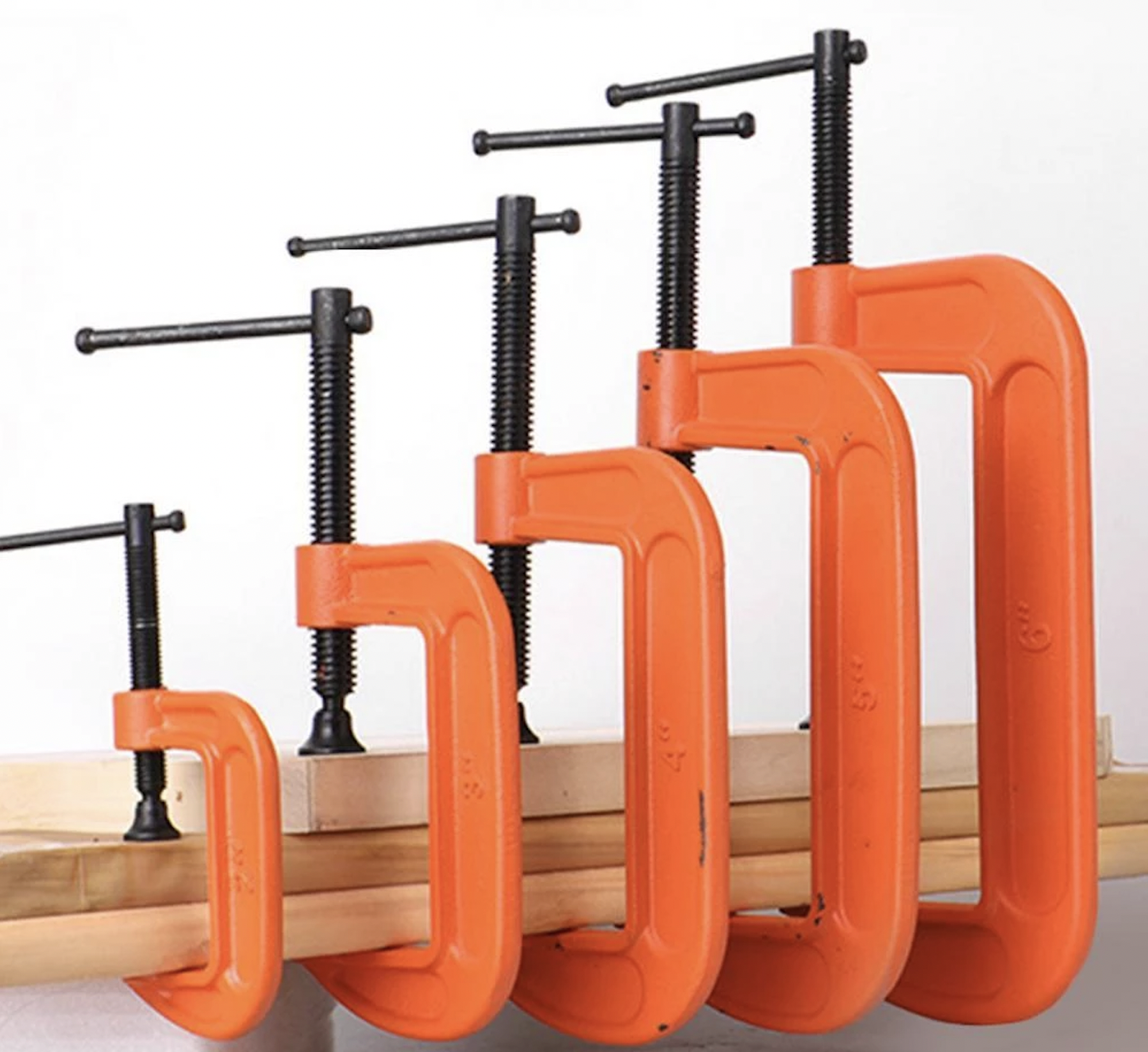
So what exactly is a bolt? At its most basic, a bolt is a clamp. It is no more than a small version of a C-clamp (or G-clamp for those of you on the other side of the pond). If you want to hold two things together temporarily, you use a C-clamp. If you want to hold them together permanently, use a bolt. Stated more technically:
“A bolt is a device that provides a clamping force between two or more surfaces such that the surfaces cannot move relative to each other under normal service loads.”
There are essentially two types of joints that bolts are asked to clamp together: Shear and Tensile. In a shear joint, the bolt is used to provide sufficient friction between two or more surfaces such that there is no movement possible between the surfaces. In a tensile joint, the bolt is used to provide sufficient preload in the joint that under normal loads there is no separation possible between the surfaces.
First, let’s talk about shear joints.
Shear Joint
A bolt uses friction to ensure that two or more objects are held together and do not move relative to each other when they are subjected to the normal forces the objects are designed for. The part about not moving is key here. A bolt must not allow ANY movement between the objects, not even a tiny bit. There must be enough friction between the objects that they cannot move at all. Even a tiny bit of movement means that the bolt has failed to do its job and the joint will eventually fail and break. Therefore, the bolt has to be strong enough and tight enough to provide the necessary friction, so we need to know exactly how much force the joint has to resist. That is step number one.
A Bolt Acts Like A Spring
So, how does a bolt provide the friction we need? A bolt is really just a simple spring, albeit a very stiff one. When you push and pull on a spring, it develops a force which is governed by the equation:
F = K x X
Where X is the amount the spring is being stretched (or compressed) and K is the stiffness of the spring. Multiply those two together and you get the force in the spring. Here’s an example: Suppose we have a spring that has a stiffness of 15 lb/in, in other words, it takes 15 lb of force to stretch or compress the spring one inch. If we want to compress this spring 2 inches, we would need:
F = 2” x 15 lb/in = 30 lb
The same thing happens in a bolt. [Editor’s note: The equation above shows the spring equation since we’re making an analogy. In reality, the relationship between force, strain, and stiffness of a metal bolt is , which is stress = elastic modulus x strain. But it’s the same idea. -DT]. When we tighten the bolt, the threads of the bolt are trying to pull the nut closer to the head of the bolt. But, the object we are trying to clamp (a steel plate, a suspension bushing, a bracket, etc.) is in the way and stops the nut from being able to get closer to the bolt head. The only way the nut can keep turning is for the bolt to stretch just like a spring. Of course, like a spring, this gets harder and harder the more you try to stretch the bolt which is why it gets harder and harder to turn a nut the more you tighten it. We can imagine a similar thing happening to the objects being clamped by the bolt; they have a stiffness as well and we can think of them as springs that instead of being stretched, are being compressed by the force of the bolt.
 , which is stress = elastic modulus x strain. But it’s the same idea. -DT]. When we tighten the bolt, the threads of the bolt are trying to pull the nut closer to the head of the bolt. But, the object we are trying to clamp (a steel plate, a suspension bushing, a bracket, etc.) is in the way and stops the nut from being able to get closer to the bolt head. The only way the nut can keep turning is for the bolt to stretch just like a spring. Of course, like a spring, this gets harder and harder the more you try to stretch the bolt which is why it gets harder and harder to turn a nut the more you tighten it. We can imagine a similar thing happening to the objects being clamped by the bolt; they have a stiffness as well and we can think of them as springs that instead of being stretched, are being compressed by the force of the bolt.
Once the bolt is tightened, the force in the bolt “spring” and the force in the object “spring” are the same and push against each other in the area under the head of the bolt. They also push against each other in the area between the two objects. This is where the friction is generated that keeps the objects from moving.

Determining The Bolt Needed For The Job
So now that we know how to use a bolt to create friction between two objects, how do we know that is enough? As I said earlier, the first thing we need to know is how much force the joint has to be able to withstand. With that knowledge, we can then determine how strong the bolt has to be, i.e. how much clamping force the bolt has to be able to provide.
Let’s do an example. Suppose we have two steel plates that are going to be bolted together and we need to be able to pull on these plates with a force of 1,000 lb. Something like this:

The amount of friction between two objects is governed by the following equation:
F_friction = mu x N
Where N is the force pushing the two objects together (the clamping force from the bolt, in this case) and mu is the “coefficient of friction” for the materials the objects are made of. When two materials are pushed against each other, the force it takes to make them slide depends on the materials. For instance, put a block of steel on a concrete surface and it will not slide very easily. Put that same block of steel on a teflon surface and it will slide much more easily. In both cases, the force (N in our equation) pushing the block against the concrete or teflon is just the weight of the block and is always the same. The difference is the coefficient of friction, which is much higher in the case of the concrete than it is in the case of the teflon.
The coefficient of friction is a number that is determined by testing different materials in a laboratory and is a number usually between 0 and 1. There are instances where the number can be higher than one but they are rare. Very sticky tires can have a mu value higher than one, for instance. Zero is also not common because that would mean there is no friction at all which I’m pretty sure would be physically impossible. In most cases though, mu will be somewhere between 0.1 and 0.6 with the majority of materials, like steel against steel, the value that most engineers use is 0.2.
Now let’s go back to our example. We now know what mu is (0.2) and we know how much friction we need (1,000 lb), but we don’t know N yet. Re-arranging our formula we can solve for N:
N = F_friction / mu
Or
N = 1000 / 0.2
Therefore
N = 5,000 lb
Now that we know how much clamp force the bolt has to be able to provide, we need to pick a bolt that is big enough to provide that much force.
Like anything else, if you tighten a bolt enough, eventually it’s going to break. There is a limit to how much clamping force a bolt can provide before it fails. Failure in this case means the bolt has stretched too far and is now longer than it was originally. If we tighten a bolt up to the point of failure and then loosen it, it will come back to the same shape and length as it was before. If we tighten a bolt beyond the point of failure then it will have permanently stretched and will be longer than it was. This is typically seen as a necking down of the bolt shank and looks a bit like this:

So how do we know how much a particular bolt can take before it fails? We need to know something called the “proof load” of the bolt. This can be easily found online and will depend on the size of the bolt and the grade, or property class, of the bolt. A 1/4-inch “grade 5” bolt will not be as strong as a 1/4-inch “grade 8 bolt,” for example, even though they are the same size. Proof load tables look something like this:

Let’s see which bolt would work for our application. Let’s look at grade 5 bolts since they are easy to find and cheap. Going down the grade 5 column we see that we do not get above 5,000 lb until we get to a ⅜-inch 16 threads per inch (⅜-16) bolt which has a max load of 6,510 lbs. It looks like this bolt would work perfectly in our example.
Determining How Much You Need To Tighten The Bolt (Torque Spec)
Now that we have chosen a bolt to hold our plates, we need to decide how much we should tighten it. There are many tables available that will tell you how much you can tighten a ⅜-16 bolt, but they make a lot of assumptions about the type of materials being clamped together, the method for tightening (hand tightening, pneumatic torque wrench, DC nut runners, etc.) and the condition of the parts (are they clean, is there some dirt or oil still on them, etc.). We want to be much more precise than that. This requires physical testing. We need to make some samples of our parts and we need to get sample bolts and nuts. It is important these samples are made as close as possible to the final manufacturing method. This means getting the samples from the same suppliers that will provide the parts once we start production.
Once we have our samples we need to run two tests on them: torque to failure and shear-load to slip. The torque to failure test will tell us what torque we need to specify and the shear-load to slip will tell us if all our calculations and assumptions were right and we have enough clamp load to resist our 1,000 lb force. Both tests require some very special and expensive equipment so we usually send it out to one of a few companies that do this type of work.
Torque to Failure
In the torque to failure test, we will assemble the parts with the bolts and nuts and then tighten the nut or bolt until it breaks. While doing this we will measure the angle, or amount of rotation of the nut or bolt, and the torque we have to apply to make the nut or bolt rotate. Plotting them against each other we get something like this:

There are 5 important areas marked on this graph: run-down, transition, elastic tightening, plastic tightening, and failure.
Rundown: This is the part where the parts are not quite pushed up against each other and the nut is still only finger tight
Transition: In this area the parts are starting to touch each other and any imperfections in the surfaces are slowly pushed flat. If the surfaces aren’t quite flat or there is some dirt between them, this is where that is pushed flat and or squashed.
Elastic Tightening: This is the important one. This is where the bolt is stretching without failing and where the clamping force is being generated.
Plastic Tightening: Here is where the bolt is starting to fail. The shank is stretching permanently (this is called plastic deformation) and starting to neck down. You can see how the clamp force is actually reducing the more you tighten the bolt.
Failure: The final area is where the bolt actually fails and snaps in two. Torque drops to zero since it now takes nothing to spin the bolt anymore.
Once we have this graph we can look at where the elastic tightening area transitions into the plastic tightening area. In this case it happens at about 30 ft-lb. From this we could conclude that we can tighten our bolt to 30 ft-lb before we start to fail the bolt. But that’s just this particular bolt. If we were to grab another bolt out of the same box of bolts and run the test again it might start to fail at a slightly different torque, maybe 30.5 ft-lb or 29.7 ft-lb — we don’t know. So, to better understand the boundaries of bolt torque, we need to do this same test a few more times because even though all the parts may have been made the exact same way, there are always minor differences between them.
Usually we will run this test six to 10 times using new parts each time. We then get six to 10 graphs which will all show a slightly different transition point between the elastic and plastic areas. We will then use statistical methods to come up with a torque below which we can ensure that no bolts will fail — within 99.999% accuracy. Let’s assume in our case the result of these calculations turns out to be 28 ft-lb. That means we can be almost guaranteed that any bolt we pick will not fail when we tighten it to this torque spec.
Tool Variability
The next thing we need to do is to understand how this bolt will be tightened in our production plant. Every tool has some variability when used. In other words when you use a torque wrench to tighten a bolt, the actual torque is never exactly what the torque wrench says. If you set a torque wrench to 28 ft-lb and tighten a bolt, the actual torque might in fact be 27.5 ft-lb or 28.2 ft-lbs. It will rarely be exactly 28 ft-lb.
How close the torque wrench can consistently get to the value you are asking for will depend on the type of tool you are using. A DC nut runner has a very high accuracy while an air impact wrench has less accuracy. Let’s suppose the torque wrench we are using has an accuracy of +/- 5%. This means if we set the wrench for 28 ft-lb, we will actually get anywhere between 26.6 and 29.4 ft-lb. That’s a range of 2.8 ft-lb overall and it means that half of the time we will be over-tightening bolts. So, if we know that we can never go over 28 ft lb without risking failing some of the bolts, and if we know the range is 2.8 ft lb, then we should target a torque of 28 – 2.8/2 = 26.6 ft-lb. That way, using the torque wrench we’ve chosen, the max we will get is 26.6 + 5% = 27.9 ft lb and the lowest we will get is 26.6 – 5% = 25.3 ft lb. Doing that will assure we never go over 28 ft-lb and we will never cause any bolts to fail.
Shear Load to Slip
We are now set to run our second and last group of tests, which is the shear load to slip. For these tests we will assemble another six to ten sets of parts using the torque spec we calculated by adjusting the torque to failure test results with tooling variability considerations (for this, we’d use super accurate, expensive torque wrenches that are constantly calibrated). So in this case, we’d torque to 26.6 ft-lbs, and then we’d use a press to push the two parts being clamped in a way that puts the bolt into shear.
As we push on each sample, we will measure the force and the position of the press. What we’re looking for is a very small jump in the position of the plate we are pushing on. This means the plate has slipped and we have reached the maximum force the joint can handle. This is the shear load to slip: the load in the shear direction required to make the joint slip. Do this for all the samples and apply the same type of statistics we used in the torque to failure tests to find the lowest shear load we could expect any future joint to be able to handle. If this load is higher than our 1,000 lb load then the joint is good and we can proceed with production. If not, then we need to go back to the drawing board and use a larger bolt.
So now that we know how much torque we need to hold the joint together, where does all that torque actually go? We know the object here is to stretch the bolt, but how much of the torque we apply is actually going to stretching the bolt? Here is a breakdown in a case where we tighten the bolt and hold the nut:

As you can see, only about 10% of the torque we apply to the bolt causes it to stretch. The other 90% goes into the friction between the bolt and the object and into the threads of the nut. [Editor’s Note: If you live in Michigan or any other rust-belt state, that figure goes from 90 to 99.99999999%. -DT].
The Tensile Joint
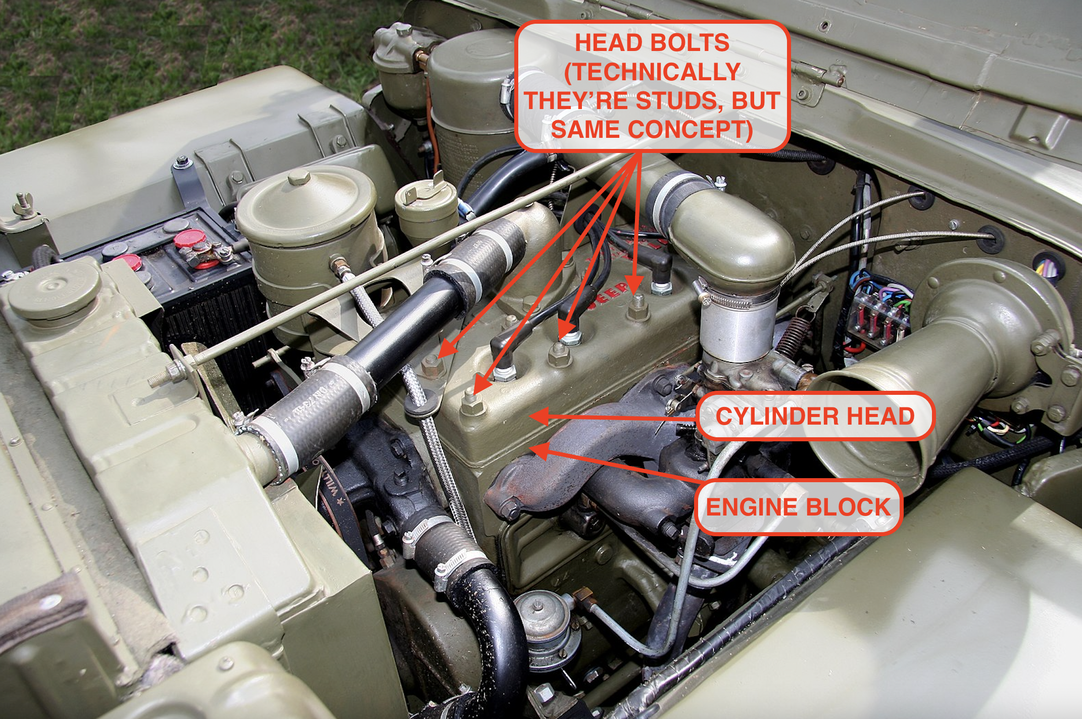
Now let’s look at the tensile joint. What happens when we have a joint that is in tension instead of shear? Cylinder head bolts are a good example of this type. Engine combustion is trying to lift the head off the block and the head bolts pull it back down to contain the pressure in the cylinders. There is nothing pushing the head sideways so there is no shear load here. In this case, we are not asking the bolts to create friction, they are instead creating a pre-load that the pressure of combustion is trying to overcome. Here is what I mean by that.

Imagine a bolt, represented by the spring above, clamping a cylinder head with a force of 1,000 lbs. That is the preload being applied by the bolt. You need to apply a force greater than 1,000 lbs to overcome this preload and cause the head to become unclamped.
Here’s another way to think about it. If I put you inside a box and then sit on it, you will have to push up on the lid with a force greater than my weight in order to lift the lid and get out of the box. If I weigh 200 lb and you can only push up with a force of 100 lb then you will never be able to lift the lid. The other part of this is that I will never know you are pushing up against the lid until you overcome my weight. I cannot feel you pushing with 100 lb of force because the lid has not moved. In the same way, a bolt clamping a cylinder head will not know that an external load is being applied until that load exceeds the preload in the bolt (1000 lb in the case of the diagram above).
This is the principle that keeps cylinder heads in place and sealed to the block. Add the clamp load of all the head bolts together and you will have the force that the combustion pressures have to overcome in order to lift the head off the block. If the pressures never exceed this total clamp load then the head will always stay in place and the seal will remain intact. This is why it’s so critical to tighten head bolts correctly. Too little torque means there isn’t enough preload in the bolts, and every time a cylinder fires, the combustion pressures can lift the head up ever so slightly and cause a small leak that will get worse and worse as time goes by.
A Look At Bolts Used For Suspension Bushings
Let’s take a look at another usage of bolts, this time in a suspension. In most cars, the suspension arms are bolted to the body of the car or to a subframe using clevis joints.

Notice that the suspension arm is being clamped on two sides by the subframe while a single bolt goes through everything and holds it all together. If we look at this joint in cross section, it might look something like this:

A key thing to remember here is that before the bolt is tightened, there is a gap in the joint to make it easier to install the bushing between the two body brackets. If it were a tight fit then it would be difficult to install on the factory floor, so these joints are always designed with a small gap like this:

As the bolt then gets tightened, the first thing that happens is the body bracket is pulled towards the bushing to close the gap. Of course, it takes some force to close this gap since we have to bend the steel of the body bracket as we tighten the bolt and that force has to be provided by the bolt. This means that not all the force in the bolt is available to provide the friction we need to keep the bushing in place. Depending on how stiff the steel of the body bracket is, this can have a significant impact on the design of the joint and the suspension engineer must take this into account.
[Editor’s note: I’d like to show how this looks on a Jeep control arm. It works the same way in a wishbone-style arm. Basically, the metal sleeve at the center of the bushing gets squished against the unibody (or in some cases, the frame/subframe), so when the suspension moves and the arm rotates, the sleeve doesn’t, causing the rubber to flex. This is how many of your suspension parts move in a quiet, controlled manner.
Here’s a look at a Jeep XJ lower control arm:

And here’s the opening in the unibody where it slots before being squeezed by a big bolt:

-DT]
On the positive side, there are now two surfaces reacting to the force coming from the suspension, so we now get twice the amount of friction force for the same clamp load coming from the bolt. Our friction equation now looks like this:
F_friction = mu x N x 2
This is a big help and means we can use a smaller bolt to do the same job as we had in our plate example above. This is called a double shear joint while the plate example was a single shear joint.
Here, as in the plate example, once we have a design, we would make sample parts and do the exact same torque to failure and shear load to slip testing to determine the installation torque and make sure the whole joint will withstand the forces we expect the suspension to endure.
Well, you’ve survived your first deep dive into the world of fasteners and lived to tell the tale. We’ve only just scratched the surface here but if you want to learn more, I can highly recommend a book called “An Introduction to the Design and Behavior of Bolted Joints” by John H. Bickford. He can take you many levels deeper than I can and should be required reading for anyone who designs bolted joints for a living.


_Motor.JPG)
Nice article. I vaguely remember something about correctly sizing shanks and threads into bolt holes and how undersized shanks were too be rejected. Clarification?
Good article.
1 petty complaint: alt + 230 is your friend for cat-noise sounding greek letters
µ µ µ
Bonus for keeping it simple and suggesting further reading.
There is no way to cover all the joint variations and improvements in an article like this thanks for basics.
I liked it!
Great write up Huibert, brought back memories of studying statics at Uni!
There’s a shipbuilder in the city I live (Hobart, Tasmania, Australia) that specialises in large – circa 300ft – all aluminium high-speed catamarans, a good friend of mine is on their structural engineering team and he tells me that the majority of their fastenings are tightened to stretch, as opposed to a torque value. I’m told that the reason for this is there can be vagaries such as friction etc when tightening to a torque value, whereas these discrepancies in clamping pressure are greatly minimised when tightening to an (albeit minuscule) pre-determined stretch amount of the bolt in question.
Why do some torque settings say something like 85 ft/lbs and then 270 degrees ? why not just a higher torque setting
The 85ft-lbs will get all the loose out of the system. The 270deg will produce a calculable amount of stretch in the bolt generating a clamping force.
Let’s say you have a 1/2-20 bolt. The 270deg is 3/4 of a turn.
A 20 threads per inch has a pitch of .05″ per revolution. 3/4 of a turn is .038″ of stretch.
https://www.srtorque.com/error-proofing-tools/digital-torque-and-angle-tools/1250-series-exacta-2-digital-torque-and-angle-wrench/why-torque-and-angle/#:~:text=Torque%20is%20an%20affordable%2C%20relatively,in%20a%20controlled%
Wow, I missed some good stuff while I was away. “Fastenating” indeed!
I suppose when people talk about “mechanic’s feel,” it’s that sense of knowing when you’re coming up on the transition from elastic to plastic tightening, and stopping before you get there? Because there is a definite change in the feel of the wrench when you reach that point, if you’re feeling for it, especially on smaller fasteners.
That only works on iron and steel. Aluminum and other lightweight material go right from “feels good” to “stripped out” Always use torque specs on lightweight materials.
Very interesting article. It got me thinking about the bolts I’ve got in my spine where they put in a plate. Wondering what the torque specs are for those guys.
Ya know, as someone with a Telecom/Psych degree, I had to take a few breaks while reading to let it all soak in. Way more complicated than I ever thought it was gonna be. I have two main takeaways from it all:
1. I was extremely lucky, as a younger me, that I never snapped a bolt (or worse) changing my tires. My technique was only to stomp down on the crowbar until it wouldn’t move. Then, I’d reset it to horizontal and jump on it until it made funny groaning noises, usually mumbling something like “that sucker ain’t doing anywhere now!”
2. I now understand why the instructions for the TV mount stand I recently bought say to not overtighten. I was worried because it’s a kinda pricey TV, but now I feel good about how it is.
Killer write-up, Sir! The old “Ya learn some new everyday” maxim could not be truer this morning.
Wheels are pretty forgiving for torque. Especially steel rims. There’s a lot of very slow linear elastic deformation and not very strict tolerances. Plenty of space to go with a bit of overkill on bolt size, too.
Now head bolts..
David, using F=k*dx is accurate, as for a bolt k=S.E/L where E is the Young modulus, S the bolt cross section and L its free length. That’s how I model bolts in FEA analyses.
Having worked in aircraft for about 30 years, this is the first I have heard that other fields are actually allowed to count on the friction of a shear joint to do the work! I am specifically forbidden from counting friction unless it is adverse, consequently, the fastener must be assumed to take the load. Realistically, we know friction prevents the motion, but regulatorily (is that a word?), we have to ignore it.
We also fasten sheets of really thin, comparably weak, materials together, so joints typically tend to use a lot of small fasteners with low torque, rather than just a couple of big ones with high torque, as that would literally extrude the thin aluminum sheets from the joint like toothpaste.
Might also want to mention that most texts suggest that the sweet spot of preload for a bolt is about 3/4 of the way up that “elastic tightening” curve. Just one more factor to consider.
Heavy machinery engineer here. We also avoid using bolts to deal with shear loads, we use dowel pins. However, the design philosophy in my field is is “bolts are cheap, slap 16 M24 there and it’ll be fine”. I do account for bolt stiffness in my FEA computations but I’ve never had any issue with the bolts load, ever.