")
Dear Autopians. It’s time. It’s time to go deep. Deep into the depths of engineering nerdom. Do you want to know the physics behind how bolts work (they work essentially like springs)? Do you wonder how automakers decide which bolt size to use? Are you curious how they come up with fastener installation torque specs? Do you wonder how much of that force you put on a ratchet actually goes into creating a clamp load versus how much is just overcoming thread friction? These are the things you will learn as we go down a path that many have tried and failed to travel. So grab the hand of the person next to you — it’s dark down there — and follow me as I guide you into the wonderful, fascinating world of the most ubiquitous and much maligned component in all of engineering: the fastener — a component more complex and interesting than most people give it credit for. Yes folks, it’s time to learn about the lowly nut and bolt.
[Welcome to Huibert Mees’s column, where the former Ford GT/Tesla Model S suspension engineer gets to write whatever he wants on The Autopian. -DT]
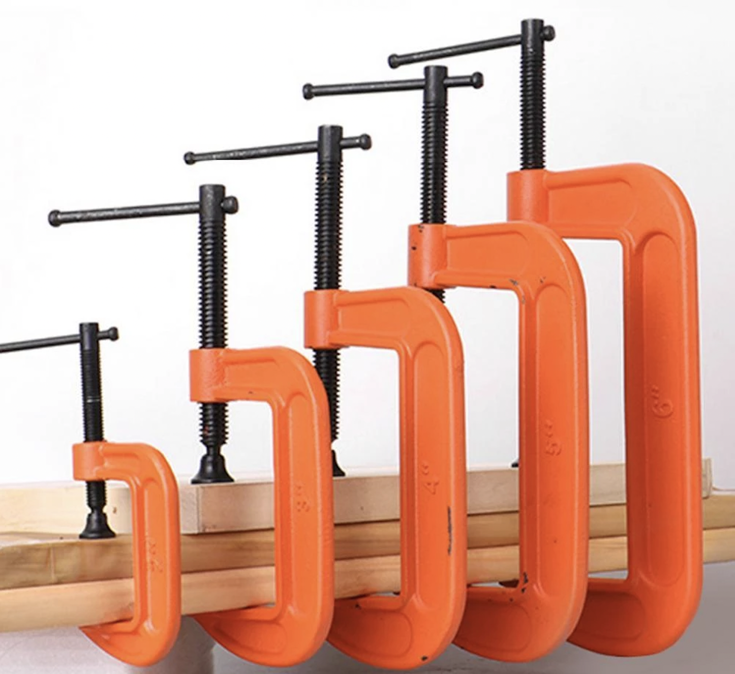
So what exactly is a bolt? At its most basic, a bolt is a clamp. It is no more than a small version of a C-clamp (or G-clamp for those of you on the other side of the pond). If you want to hold two things together temporarily, you use a C-clamp. If you want to hold them together permanently, use a bolt. Stated more technically:
“A bolt is a device that provides a clamping force between two or more surfaces such that the surfaces cannot move relative to each other under normal service loads.”
There are essentially two types of joints that bolts are asked to clamp together: Shear and Tensile. In a shear joint, the bolt is used to provide sufficient friction between two or more surfaces such that there is no movement possible between the surfaces. In a tensile joint, the bolt is used to provide sufficient preload in the joint that under normal loads there is no separation possible between the surfaces.
First, let’s talk about shear joints.
Shear Joint
A bolt uses friction to ensure that two or more objects are held together and do not move relative to each other when they are subjected to the normal forces the objects are designed for. The part about not moving is key here. A bolt must not allow ANY movement between the objects, not even a tiny bit. There must be enough friction between the objects that they cannot move at all. Even a tiny bit of movement means that the bolt has failed to do its job and the joint will eventually fail and break. Therefore, the bolt has to be strong enough and tight enough to provide the necessary friction, so we need to know exactly how much force the joint has to resist. That is step number one.
A Bolt Acts Like A Spring
So, how does a bolt provide the friction we need? A bolt is really just a simple spring, albeit a very stiff one. When you push and pull on a spring, it develops a force which is governed by the equation:
F = K x X
Where X is the amount the spring is being stretched (or compressed) and K is the stiffness of the spring. Multiply those two together and you get the force in the spring. Here’s an example: Suppose we have a spring that has a stiffness of 15 lb/in, in other words, it takes 15 lb of force to stretch or compress the spring one inch. If we want to compress this spring 2 inches, we would need:
F = 2” x 15 lb/in = 30 lb
The same thing happens in a bolt. [Editor’s note: The equation above shows the spring equation since we’re making an analogy. In reality, the relationship between force, strain, and stiffness of a metal bolt is , which is stress = elastic modulus x strain. But it’s the same idea. -DT]. When we tighten the bolt, the threads of the bolt are trying to pull the nut closer to the head of the bolt. But, the object we are trying to clamp (a steel plate, a suspension bushing, a bracket, etc.) is in the way and stops the nut from being able to get closer to the bolt head. The only way the nut can keep turning is for the bolt to stretch just like a spring. Of course, like a spring, this gets harder and harder the more you try to stretch the bolt which is why it gets harder and harder to turn a nut the more you tighten it. We can imagine a similar thing happening to the objects being clamped by the bolt; they have a stiffness as well and we can think of them as springs that instead of being stretched, are being compressed by the force of the bolt.
 , which is stress = elastic modulus x strain. But it’s the same idea. -DT]. When we tighten the bolt, the threads of the bolt are trying to pull the nut closer to the head of the bolt. But, the object we are trying to clamp (a steel plate, a suspension bushing, a bracket, etc.) is in the way and stops the nut from being able to get closer to the bolt head. The only way the nut can keep turning is for the bolt to stretch just like a spring. Of course, like a spring, this gets harder and harder the more you try to stretch the bolt which is why it gets harder and harder to turn a nut the more you tighten it. We can imagine a similar thing happening to the objects being clamped by the bolt; they have a stiffness as well and we can think of them as springs that instead of being stretched, are being compressed by the force of the bolt.
Once the bolt is tightened, the force in the bolt “spring” and the force in the object “spring” are the same and push against each other in the area under the head of the bolt. They also push against each other in the area between the two objects. This is where the friction is generated that keeps the objects from moving.

Determining The Bolt Needed For The Job
So now that we know how to use a bolt to create friction between two objects, how do we know that is enough? As I said earlier, the first thing we need to know is how much force the joint has to be able to withstand. With that knowledge, we can then determine how strong the bolt has to be, i.e. how much clamping force the bolt has to be able to provide.
Let’s do an example. Suppose we have two steel plates that are going to be bolted together and we need to be able to pull on these plates with a force of 1,000 lb. Something like this:

The amount of friction between two objects is governed by the following equation:
F_friction = mu x N
Where N is the force pushing the two objects together (the clamping force from the bolt, in this case) and mu is the “coefficient of friction” for the materials the objects are made of. When two materials are pushed against each other, the force it takes to make them slide depends on the materials. For instance, put a block of steel on a concrete surface and it will not slide very easily. Put that same block of steel on a teflon surface and it will slide much more easily. In both cases, the force (N in our equation) pushing the block against the concrete or teflon is just the weight of the block and is always the same. The difference is the coefficient of friction, which is much higher in the case of the concrete than it is in the case of the teflon.
The coefficient of friction is a number that is determined by testing different materials in a laboratory and is a number usually between 0 and 1. There are instances where the number can be higher than one but they are rare. Very sticky tires can have a mu value higher than one, for instance. Zero is also not common because that would mean there is no friction at all which I’m pretty sure would be physically impossible. In most cases though, mu will be somewhere between 0.1 and 0.6 with the majority of materials, like steel against steel, the value that most engineers use is 0.2.
Now let’s go back to our example. We now know what mu is (0.2) and we know how much friction we need (1,000 lb), but we don’t know N yet. Re-arranging our formula we can solve for N:
N = F_friction / mu
Or
N = 1000 / 0.2
Therefore
N = 5,000 lb
Now that we know how much clamp force the bolt has to be able to provide, we need to pick a bolt that is big enough to provide that much force.
Like anything else, if you tighten a bolt enough, eventually it’s going to break. There is a limit to how much clamping force a bolt can provide before it fails. Failure in this case means the bolt has stretched too far and is now longer than it was originally. If we tighten a bolt up to the point of failure and then loosen it, it will come back to the same shape and length as it was before. If we tighten a bolt beyond the point of failure then it will have permanently stretched and will be longer than it was. This is typically seen as a necking down of the bolt shank and looks a bit like this:

So how do we know how much a particular bolt can take before it fails? We need to know something called the “proof load” of the bolt. This can be easily found online and will depend on the size of the bolt and the grade, or property class, of the bolt. A 1/4-inch “grade 5” bolt will not be as strong as a 1/4-inch “grade 8 bolt,” for example, even though they are the same size. Proof load tables look something like this:

Let’s see which bolt would work for our application. Let’s look at grade 5 bolts since they are easy to find and cheap. Going down the grade 5 column we see that we do not get above 5,000 lb until we get to a ⅜-inch 16 threads per inch (⅜-16) bolt which has a max load of 6,510 lbs. It looks like this bolt would work perfectly in our example.
Determining How Much You Need To Tighten The Bolt (Torque Spec)
Now that we have chosen a bolt to hold our plates, we need to decide how much we should tighten it. There are many tables available that will tell you how much you can tighten a ⅜-16 bolt, but they make a lot of assumptions about the type of materials being clamped together, the method for tightening (hand tightening, pneumatic torque wrench, DC nut runners, etc.) and the condition of the parts (are they clean, is there some dirt or oil still on them, etc.). We want to be much more precise than that. This requires physical testing. We need to make some samples of our parts and we need to get sample bolts and nuts. It is important these samples are made as close as possible to the final manufacturing method. This means getting the samples from the same suppliers that will provide the parts once we start production.
Once we have our samples we need to run two tests on them: torque to failure and shear-load to slip. The torque to failure test will tell us what torque we need to specify and the shear-load to slip will tell us if all our calculations and assumptions were right and we have enough clamp load to resist our 1,000 lb force. Both tests require some very special and expensive equipment so we usually send it out to one of a few companies that do this type of work.
Torque to Failure
In the torque to failure test, we will assemble the parts with the bolts and nuts and then tighten the nut or bolt until it breaks. While doing this we will measure the angle, or amount of rotation of the nut or bolt, and the torque we have to apply to make the nut or bolt rotate. Plotting them against each other we get something like this:

There are 5 important areas marked on this graph: run-down, transition, elastic tightening, plastic tightening, and failure.
Rundown: This is the part where the parts are not quite pushed up against each other and the nut is still only finger tight
Transition: In this area the parts are starting to touch each other and any imperfections in the surfaces are slowly pushed flat. If the surfaces aren’t quite flat or there is some dirt between them, this is where that is pushed flat and or squashed.
Elastic Tightening: This is the important one. This is where the bolt is stretching without failing and where the clamping force is being generated.
Plastic Tightening: Here is where the bolt is starting to fail. The shank is stretching permanently (this is called plastic deformation) and starting to neck down. You can see how the clamp force is actually reducing the more you tighten the bolt.
Failure: The final area is where the bolt actually fails and snaps in two. Torque drops to zero since it now takes nothing to spin the bolt anymore.
Once we have this graph we can look at where the elastic tightening area transitions into the plastic tightening area. In this case it happens at about 30 ft-lb. From this we could conclude that we can tighten our bolt to 30 ft-lb before we start to fail the bolt. But that’s just this particular bolt. If we were to grab another bolt out of the same box of bolts and run the test again it might start to fail at a slightly different torque, maybe 30.5 ft-lb or 29.7 ft-lb — we don’t know. So, to better understand the boundaries of bolt torque, we need to do this same test a few more times because even though all the parts may have been made the exact same way, there are always minor differences between them.
Usually we will run this test six to 10 times using new parts each time. We then get six to 10 graphs which will all show a slightly different transition point between the elastic and plastic areas. We will then use statistical methods to come up with a torque below which we can ensure that no bolts will fail — within 99.999% accuracy. Let’s assume in our case the result of these calculations turns out to be 28 ft-lb. That means we can be almost guaranteed that any bolt we pick will not fail when we tighten it to this torque spec.
Tool Variability
The next thing we need to do is to understand how this bolt will be tightened in our production plant. Every tool has some variability when used. In other words when you use a torque wrench to tighten a bolt, the actual torque is never exactly what the torque wrench says. If you set a torque wrench to 28 ft-lb and tighten a bolt, the actual torque might in fact be 27.5 ft-lb or 28.2 ft-lbs. It will rarely be exactly 28 ft-lb.
How close the torque wrench can consistently get to the value you are asking for will depend on the type of tool you are using. A DC nut runner has a very high accuracy while an air impact wrench has less accuracy. Let’s suppose the torque wrench we are using has an accuracy of +/- 5%. This means if we set the wrench for 28 ft-lb, we will actually get anywhere between 26.6 and 29.4 ft-lb. That’s a range of 2.8 ft-lb overall and it means that half of the time we will be over-tightening bolts. So, if we know that we can never go over 28 ft lb without risking failing some of the bolts, and if we know the range is 2.8 ft lb, then we should target a torque of 28 – 2.8/2 = 26.6 ft-lb. That way, using the torque wrench we’ve chosen, the max we will get is 26.6 + 5% = 27.9 ft lb and the lowest we will get is 26.6 – 5% = 25.3 ft lb. Doing that will assure we never go over 28 ft-lb and we will never cause any bolts to fail.
Shear Load to Slip
We are now set to run our second and last group of tests, which is the shear load to slip. For these tests we will assemble another six to ten sets of parts using the torque spec we calculated by adjusting the torque to failure test results with tooling variability considerations (for this, we’d use super accurate, expensive torque wrenches that are constantly calibrated). So in this case, we’d torque to 26.6 ft-lbs, and then we’d use a press to push the two parts being clamped in a way that puts the bolt into shear.
As we push on each sample, we will measure the force and the position of the press. What we’re looking for is a very small jump in the position of the plate we are pushing on. This means the plate has slipped and we have reached the maximum force the joint can handle. This is the shear load to slip: the load in the shear direction required to make the joint slip. Do this for all the samples and apply the same type of statistics we used in the torque to failure tests to find the lowest shear load we could expect any future joint to be able to handle. If this load is higher than our 1,000 lb load then the joint is good and we can proceed with production. If not, then we need to go back to the drawing board and use a larger bolt.
So now that we know how much torque we need to hold the joint together, where does all that torque actually go? We know the object here is to stretch the bolt, but how much of the torque we apply is actually going to stretching the bolt? Here is a breakdown in a case where we tighten the bolt and hold the nut:

As you can see, only about 10% of the torque we apply to the bolt causes it to stretch. The other 90% goes into the friction between the bolt and the object and into the threads of the nut. [Editor’s Note: If you live in Michigan or any other rust-belt state, that figure goes from 90 to 99.99999999%. -DT].
The Tensile Joint
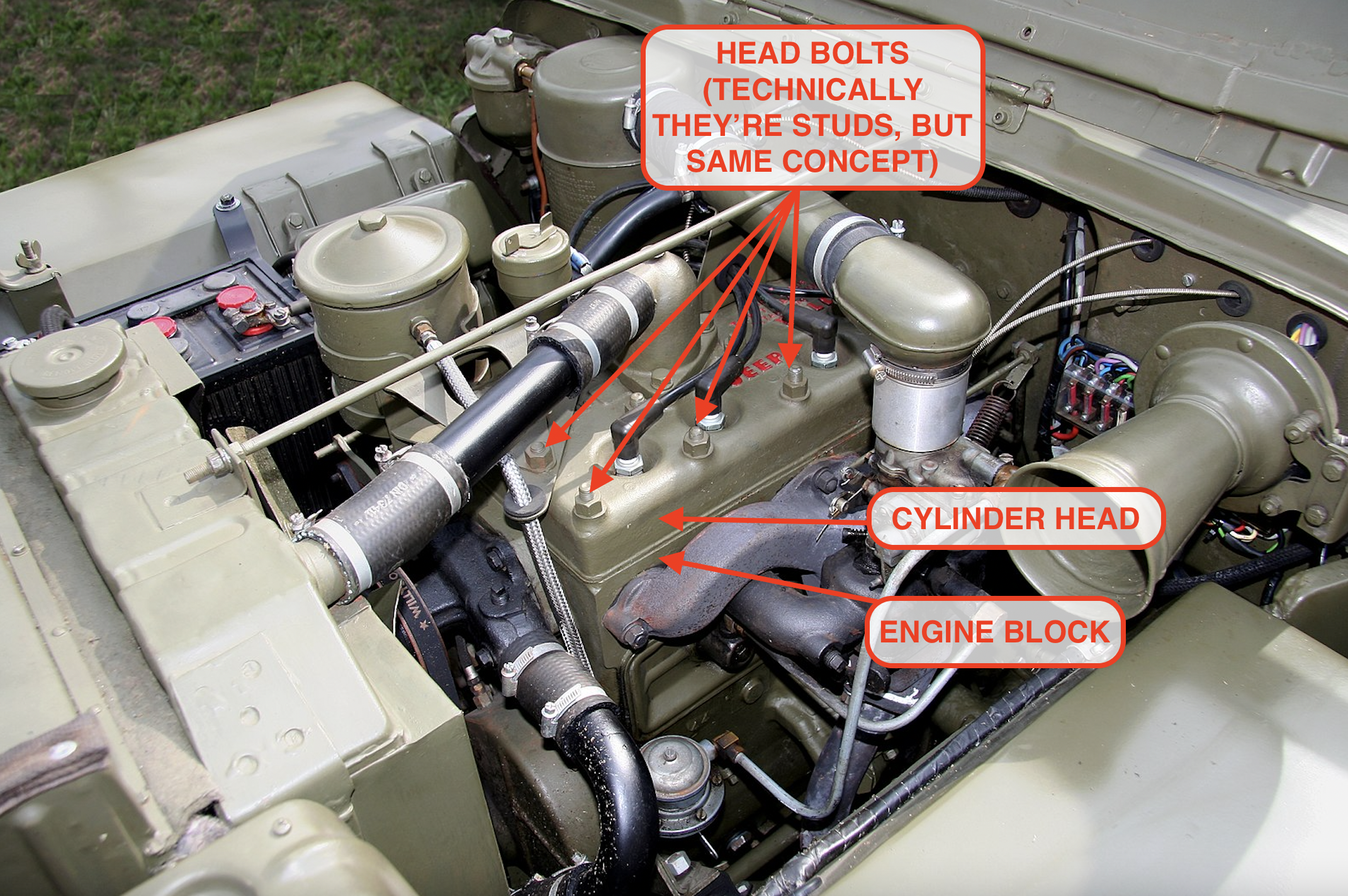
Now let’s look at the tensile joint. What happens when we have a joint that is in tension instead of shear? Cylinder head bolts are a good example of this type. Engine combustion is trying to lift the head off the block and the head bolts pull it back down to contain the pressure in the cylinders. There is nothing pushing the head sideways so there is no shear load here. In this case, we are not asking the bolts to create friction, they are instead creating a pre-load that the pressure of combustion is trying to overcome. Here is what I mean by that.

Imagine a bolt, represented by the spring above, clamping a cylinder head with a force of 1,000 lbs. That is the preload being applied by the bolt. You need to apply a force greater than 1,000 lbs to overcome this preload and cause the head to become unclamped.
Here’s another way to think about it. If I put you inside a box and then sit on it, you will have to push up on the lid with a force greater than my weight in order to lift the lid and get out of the box. If I weigh 200 lb and you can only push up with a force of 100 lb then you will never be able to lift the lid. The other part of this is that I will never know you are pushing up against the lid until you overcome my weight. I cannot feel you pushing with 100 lb of force because the lid has not moved. In the same way, a bolt clamping a cylinder head will not know that an external load is being applied until that load exceeds the preload in the bolt (1000 lb in the case of the diagram above).
This is the principle that keeps cylinder heads in place and sealed to the block. Add the clamp load of all the head bolts together and you will have the force that the combustion pressures have to overcome in order to lift the head off the block. If the pressures never exceed this total clamp load then the head will always stay in place and the seal will remain intact. This is why it’s so critical to tighten head bolts correctly. Too little torque means there isn’t enough preload in the bolts, and every time a cylinder fires, the combustion pressures can lift the head up ever so slightly and cause a small leak that will get worse and worse as time goes by.
A Look At Bolts Used For Suspension Bushings
Let’s take a look at another usage of bolts, this time in a suspension. In most cars, the suspension arms are bolted to the body of the car or to a subframe using clevis joints.

Notice that the suspension arm is being clamped on two sides by the subframe while a single bolt goes through everything and holds it all together. If we look at this joint in cross section, it might look something like this:

A key thing to remember here is that before the bolt is tightened, there is a gap in the joint to make it easier to install the bushing between the two body brackets. If it were a tight fit then it would be difficult to install on the factory floor, so these joints are always designed with a small gap like this:

As the bolt then gets tightened, the first thing that happens is the body bracket is pulled towards the bushing to close the gap. Of course, it takes some force to close this gap since we have to bend the steel of the body bracket as we tighten the bolt and that force has to be provided by the bolt. This means that not all the force in the bolt is available to provide the friction we need to keep the bushing in place. Depending on how stiff the steel of the body bracket is, this can have a significant impact on the design of the joint and the suspension engineer must take this into account.
[Editor’s note: I’d like to show how this looks on a Jeep control arm. It works the same way in a wishbone-style arm. Basically, the metal sleeve at the center of the bushing gets squished against the unibody (or in some cases, the frame/subframe), so when the suspension moves and the arm rotates, the sleeve doesn’t, causing the rubber to flex. This is how many of your suspension parts move in a quiet, controlled manner.
Here’s a look at a Jeep XJ lower control arm:

And here’s the opening in the unibody where it slots before being squeezed by a big bolt:

-DT]
On the positive side, there are now two surfaces reacting to the force coming from the suspension, so we now get twice the amount of friction force for the same clamp load coming from the bolt. Our friction equation now looks like this:
F_friction = mu x N x 2
This is a big help and means we can use a smaller bolt to do the same job as we had in our plate example above. This is called a double shear joint while the plate example was a single shear joint.
Here, as in the plate example, once we have a design, we would make sample parts and do the exact same torque to failure and shear load to slip testing to determine the installation torque and make sure the whole joint will withstand the forces we expect the suspension to endure.
Well, you’ve survived your first deep dive into the world of fasteners and lived to tell the tale. We’ve only just scratched the surface here but if you want to learn more, I can highly recommend a book called “An Introduction to the Design and Behavior of Bolted Joints” by John H. Bickford. He can take you many levels deeper than I can and should be required reading for anyone who designs bolted joints for a living.


_Motor.JPG)
As someone who has done a few handfuls of bolted joint analyses and in-house fastener testing for them, this article is pretty good and aligns with my experiences.
One thing to really highlight from your article is that getting an accurate idea of the actual relationship between clamp load and torque in-situ really does require testing. On these types of articles folks like to ask “well how does xyz affect how I should torque the bolts on my car?” and the answer is invariably, “it will require more [or less] torque but the magnitude is unknowable.”
Clean your bolts and threads folks. When reinstalling bolts you should always be aiming to recreate the factory conditions of a clean, dry bolt and nut (there are some rare conditions when lubricating oil or loctite are used in the factory, this can be tricky to track down and is not always captured by repair manuals), and stick to the factory torque spec unless that is known at-large to have been insufficient (looking at you, 7MGTE head bolts).
One thing to add that might be of automotive related interest, while vehicle manufacturers don’t use Loc-Tite that often power tool manufacturers love it so if you have any plans for opening up impact guns or other similar things be prepared to meet resistance.
DIfference in engineering mentality
You can take a Toyota apart with a 10MM, 12MM, 14MM and a 17MM socket
BMW takes everything from an 8MM thru 24MM and every size in between
Never a 21.
Did I miss something? I’m used to seeing a margin of safety factor added to the calculations. Perhaps using the lower range of the torque wrench tolerance as the article explains suffices, but it seems safer to apply a safety factor such that the bolt will never see more than 80% of its load capability.
“In the same way, a bolt clamping a cylinder head will not know that an external load is being applied until that load exceeds the preload in the bolt (1000 lb in the case of the diagram above).”
Technically, this is only correct if the bolted member stiffness is orders of magnitude stiffer than the stiffness of the fastener. In a real bolted joint loaded in tension, the clamped member(s) are not infinitely stiff and the external load applied to the joint will both reduce the clamping load and increase the load in the fastener. A real joint might have a member stiffness 4x the fastener stiffness, so that 20% of the external load is taken up by the fastener and 80% of the load is taken up by reducing the clamp load in the joint. This can be beneficial for fatigue life since the fastener will see a fraction of the actual external load applied. The stiffness is dependent on the materials used as well as the geometry of the joint.
In the other extreme case, where the fastener is orders of magnitude stiffer than the bolted members, all the external load will increase the load in the fastener and the clamp load will remain the same.
Did anyone else notice how deeply weird the “object”, “spring”, and “bolt” graphics for this article are? I’ve never seen any mechanism quite like it. Is it a spring set in holes through two pieces of solid material all held together with a nut and bolt? To what end? It sure seems like you’d need a bushing in there or something to stop things from binding during assembly. Also, is compression modulus just another term for springiness? I am confused and have questions.
I concede it certainly could be the copious quantities of cannabis I consumed last night causing my confusion, but confused I am. Thanks for that JT. 🙂
Perhaps I should RTFA before asking flippant questions. (Flame on!)
Each of the 1/2″, grade 8 bolts holding my winch plate to the front of my truck’s frame has a load rating of 16,790 lbs. 16,790 x 8 = 134,320 lbs. That’s not taking into consideration the triangulation attaching the plate to the tow hook mounts. The likelihood of my 10,000 lb winch pulling the plate (and thus front bumper) off my truck is miniscule. Yet, you see it happen due to poor engineering and poor maintenance. Even a shock load should break the 36,000 lb rope long before damaging the truck. Good bolts are cheap insurance.
So, how does threadlocker figure into this? If I’m not sure about how accurate my torque wrench is, can I throw some Loctite Blue in there “just to be safe,” or does the wet threadlocker change the thread friction during fastening and make it so that all bets are off with regard to torque? Or is it irrelevant, because threadlocker only helps with vibration and does nothing to increase clamping force?
Threadlocker will act as a lubricant as the bolt is torqued so you would need to torque your bolt less for the same amount of clamping force. How much everything changes I have no idea. I’ve heard changes because of lubrication is why some things are torqued by degrees of rotation.
We need another one of these that explains how the same principles apply to properly securing a load into your truck bed!
So, for a follow-up, can we dive into the differences in tensile load achieved using new threads vs. rusty threads, vs. chased threads vs. re-tapped threads? And then you have the capability of various analogs for bolt tension measurement e.g. DC torque wrench, click style, split beam, ultrasonic.
“Fastenating” — I see what you did there!
Suggested correction:
In the four-part Tensile Joint diagram, the third red label should (I think) read “EXTERNAL LOAD = 1-1000 LBF” rather than “PRE-LOAD = …”. (Presumably the pre-load remains constant as the external load varies within the target range?)
Fine article.
Nice catch.
That’s Torch’s mistake (and of course, mine as the editor). He’s fixing it now.
For future corrections/typos, is a comment the best means of communicating, email via tips@autopian.com, or ???
I also had a *very* weird struggle while logging in and commenting upon this particular article. I’ll do some more diagnosis if there’s a venue for web site quirks.
Generally, the site looks to be going very well — I can’t imagine what it’s been like on your end!
Nice article & great new perspective. I always just thought of bolts and screws as being simple machines in the “inclined plane” category. I never really considered them as springs, but now I am enlightened.
Thanks!
is it friction or is the bolt in double shear? I have never looked at friction when sizing a bolt because it’s unpredictable. this post needs more free body diagrams
In a properly designed joint, it’s always friction. Things that are in shear should be attached with a pin. That doesn’t mean that bolts are never used in shear, but not in places were they are being loaded to more than a small fraction of their potential.
Because of friction the bolt is in double shear.
With no friction (meaning the plates that cause the shear are not touching) you don’t have a double shear condition. Without specifically looking it up, I believe you’d have some weird, quasi-double/single shear situation where it would shift back and forth between the two conditions and would be difficult to calculate.
My view is that in a properly designed joint, friction is doing all the work. There should be no shear loading of the bolt. I know some engineers will use a bolt as a pin and load it in shear but in my experience, as soon as you do that you will eventually see joint failure. Shear loading the bolt suggests there is motion between the surface otherwise the parts would never be able to push sideways on the bolt. Motion in a joint is the first step towards failure. It only gets worse from there. At least that is my experience.
Good article. As I got into it I started to wonder who proofreads the deep engineering stuff, then I remembered David is an engineer (now that he’s an editor/writer, would he be a lapsed engineer, similar to a lapsed Catholic?)
Anyways. Like I said, good article, but a suggestion? When the diagrams get busy (such as the one that shows where all the points of friction are) maybe just use a color code showing what is where instead of arrows all going everywhere?
Nice writeup! You could make an entire series of engineering articles on this topic. In my experience with industrial compressors, the thornier part of the bolted joint problem is in defining the criteria for determining the quantity and spacing of the fasteners. Say I have a circular bolt pattern holding a cover on an opening. I can easily find the total load required to secure the cover, but deciding on what size fastener and how many means you have to analyze the load distribution created by the point loads from each fastener. Too few fasteners and you can create a leak path, but too many creates additional manufacturing cost and maintenance effort for your end user. I’d love to hear more on how this differs on engines.
This is the kind of stuff I missed out on because I didn’t take mechanical engineering classes at my high school. (Yes, I went to the kind of high school that offered ME classes.) Great reading!
Thanks Huibert! I think this is going to be another article that I point my (very well trained and experienced) engineering colleagues to from time to time. I’ve already used the one on the GT40 suspension arm to illustrate casting issues.
Bolted joints are one of the hardest subjects to grasp in my experience. I think a big part of the difficulty is that we expect them to be simple because we’ve all been using them since we got our grubby toddler handson our first Fisher Price tool sets. We think we know how they work, but it turns out we’ve been mostly using them wrong, and just getting away with slipping joints, sheared thread sections, bolt bending and the rest of the cardinal sins. But when you get into real critical applications where you can’t just use bigger bolts and more torque, you need this kind of deep dive. You know things are getting serious when you see an extra fine threaded cobalt bolt with a spline wrenching feature…
Interesting. It seems like it would generally follow, then, that the more exotic the fastener the more important it is to torque that thing correctly. When you see the aforementioned splined cobalt extra-fine bolt, you know that someone put extra special effort into making sure that that joint isn’t going anywhere—and they were probably running up against some design limitations too, so the margin for error is probably smaller.
So what is the affect of all the time, dirt and oil that ends up on my bolt when I replace the head gasket on my shitbox that I got after seeing it on my favorite website? If chiltons says 30lbs, is that good enough on my torque wrench? Or do I need to adjust that based on the conditions I see?
You’re right that it makes a difference, but how to quantify it is pretty much impossible. Manufacturers spec “friction modifiers” that raise or lower the friction between the threads and then require more or less torque applied to get proper tension. The number the head bolt/stud manufacturer specs should account for anti-seize, for example. But a greasy bolt into a dirty head is basically just a guess as to which one is raising or lowering the friction more.
That’s when you go back and re-torque later on.
Or clean your shitbox’s engine well before doing any torquing. Chase threads, use a case of carb cleaner, etc.
Always make sure everything – bolts, nuts, and the surfaces they sit against – are clean and dry before putting the engine back together. After that, follow the recommended torque, either Chilton or the manufacturer. It’s OK to use your torque wrench. I baby my torque wrenches. Never drop them, never use them as a pry bar, and never remove bolts with them. I also always dial the torque setting back to the lowest level before putting it back in the toolbox. That way the parts and springs inside will never take a set. That’s about the best you can do to make sure your tools stay as accurate as possible.
Torqued to spec or cross threaded, tight is tight.
Tom, I hope you are being sarcastic here! Cross threaded may get you tight but it definitely will not achieve the clamp load needed for the joint to function properly. And, the damaged threads may not hold up over time and the bolt may slowly loosen.
I was hoping he’d cover this subject more.
These days most head bolts use a combination of torque wrenching to spec, then adding x angle of rotation- precisely because of issues like your example.
That said,if yours specifies a torque number and nothing else, it’s safe to assume that’s with clean -but not lubricated- threads and it will be fine.
I’m curious if anyone has other thoughts
The manual for a Peugeot 307 whose head gasket I changed recently asked for lubricated bolts and cleaned threads. So I chased the threads with a tap and used some oil on the bolts. They recommended an anti seize but I felt squirmish at the idea of introducing a lubricant in the engine that wasn’t engine oil.
For a longer exploration of bolts for the layman, read “Screw To Win” aka “Nuts, Bolts, and Fasteners” by Carrol Smith.
Thanks for the recommendation! I’d heard of his books for years, but never delved into them, as I wondered if they’d be too technical for a non-pro.
Plus, *another* Carrol in racing? Who doesn’t appreciate that?!
Another book that may be of interest is “One Good Turn” by Witold Rybczynski. Essentially the history of the screw, and all the things that humans are able to do because of it. Think about a lathe or a microscope, they need consistent threaded rods to control their function predictably. It’s a really interesting read.
Great stuff! Brought me back to Engineering school. I never used that part my Engineering degrees, but it was a good refresher.
And please:
NO THREADS IN THE SHEAR PLANE!
Your effective cross sectional area is reduced and thread peaks make terrible contact surfaces.
This is only relevant after the joint has already slipped.
Or you’re relying on the bolt(s) to pin your joint.
The obvious question here is what is the effect of lubrication on thread friction and torque. Besides the obvious examples of grease and anti seize, liquid thread locker like Loctite also has a lubricating effect that needs to be allowed for in the torque wrench setting.
It has a direct effect so if you know there will be lubrication or some coating then all the testing needs to be done with the same coatings in place or the results will not be correct.
k-factor is a huge variable. Dirt, oil, etc was mentioned in the article but torque can vary 15-20% on a dry vice wet fastener. A higher nut value requires a lower torque, which is counter intuitive and not necessarily common knowledge.
Great article! Makes me further realize how finely engineered cars and in particular, bolts, really are. Clearly, only a complete buffoon would drive a car (or Jeep) with significantly rusty fasteners. Certainly no engineer would make that kind of mistake.
Wow, great article. Now I understand why my dad yelled at me so much for my application of brute force to any engine bolts. Especially when I twisted off a bolt head on a valve cover. Well that and I was a mechanical dufus as a teen.
This article…..drove me nuts (ba-dum-tss).
Seriously, I love this. The idea of doing a deep analytical dive into something most of us take for granted is the kind of mind-opening edutainment that makes one’s day notably better.
That was truly interesting. And it made sense to me. Didn’t expect that!
I’m right there with you. I barely made it through college algebra and physics but was able to understand most everything so thank you for dumbing it down to my level. As a native rust-belter I have to agree with DT’s assessment of 99.999% as the correct number.