
Stick your head underneath a car, look near each of the four wheels, and you will see a complicated looking bunch of parts that make up the car’s suspension system. To some this may look overwhelming. There are links, rods, arms, ball joints, springs, dampers, lions, tigers, bears — oh my! In the front there is the steering system, and inside each wheel there are brake rotors, calipers and hoses. There are electrical wires sticking out of weird places. It’s enough to make your head spin! What does all this stuff do and why does it have to look so complicated? Inquiring minds want to know! Well, dear reader, we at The Autopian are here to help you out. Let’s talk about how suspensions work.
[Editor’s note: Hi, David Tracy here. I told Huibert — our seasoned suspension engineer who led design on vehicles you may know like the Ford GT and Tesla Model S — that he can nerd out as much as he wants on The Autopian. So he decided in this article to teach folks the basics of suspension design. Enjoy! -DT]
Suspension Is All About Controlling Motion Of The ‘Knuckle’
There are many things a car’s suspension has to do. It holds the car off the ground. It sends the car in the direction the driver wants (most of the time!). It keeps bumps and potholes in the road from loosening your fillings. It handles all the forces from acceleration, braking, and cornering. It makes sure that under normal conditions, all four tires are touching the ground. It makes sure that when things do go wrong, they go wrong in as safe a way as possible.
As you can see, there’s a lot going on on an average drive, but all of these functions boil down to one single job: The suspension’s purpose is to control the motion of the knuckle. That’s it! Now, while that sounds simple, it is in the WAY the suspension does this that the magic happens and where the skills of the suspension designers and development engineers shine through.
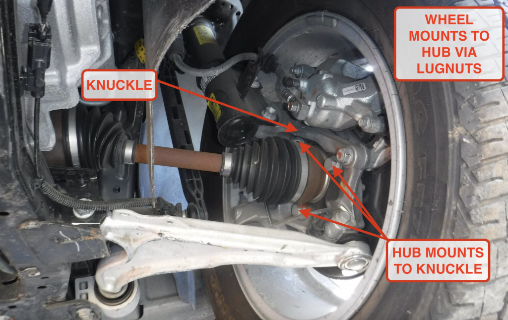
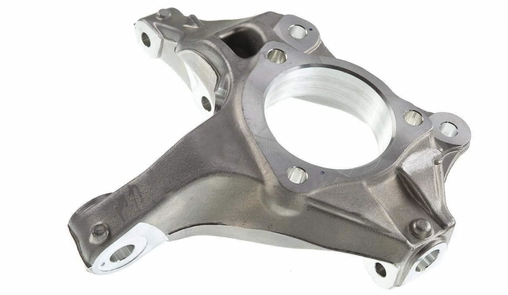
Let’s break this down a bit. The knuckle is an oddly-shaped piece of metal to which the wheel is attached. You can see the knuckle in the image above.
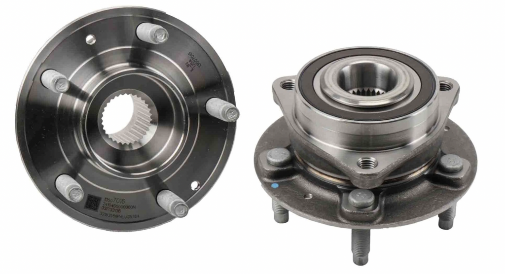
Notice those three bolts on the inside of the knuckle — those attach the wheel hub to the knuckle. That hub, shown below, includes the lug studs (five in this case) that the wheels mount to (you thread the lugnuts onto those studs to hold your wheel on) as well as a bearing that lets the wheel spin:
Since acceleration, braking, cornering, and all of that important stuff happens between the tire and the road, controlling what the wheels and tires do is the only job the suspension has. And since the wheel is bolted to the hub bearing, which is bolted to the knuckle, motion of the wheel is dictated by motion of the knuckle.
In a very basic sense, the knuckle is just an object, and this object, like any other object, has six degrees of freedom. What I mean is that it can move in six different ways. Let’s dig deeper.
Suspensions Are All About Constraining The Knuckle To One ‘Degree Of Freedom’ — Up-And-Down
Picture an object floating in the air. It could be anything: a rock, a piece of paper, a book — anything. It just happens to be floating in the air like an astronaut in space. This object can move forward or backward, it can move up or down, or it can move left or right. It can also rotate to the left or to the right (kind of like if the astronaut did a somersault). It can rotate forward or backward (like if the astronaut did a frontflip or backflip). Or it can turn left and right (like if the astronaut did a pirouette).
Let’s follow the official Society of Automotive Engineers coordinate system and call moving forward and backward moving along the X, or longitudinal axis (picture the axis as a line). The object can move forward along that line or it can move backward along that line. Let’s now call movement to the left or to the right as movement along the Y, or lateral axis, and we’ll call movement up and down movement in the Z or vertical direction (along the Z axis).
We can also define the rotating motions in a similar way where “roll” (like the summersault) represents rotation around the X axis (you can imagine that, to spin around a fore-aft line, the astronaut would end up spinning to their left or right), “pitch” (like the frontflip or backflip) is rotation around the Y axis (spinning around a line that’s oriented left-right means the astronaut falls forward or back) and “yaw” (like the pirouette) is rotation around the Z direction (to spin around a line going up-down, the astronaut pirouettes). Graphically this is represented by this Jason Torchinsky-created image of an American Gemini space capsule, which was able to move unconstrained on all these axes:

Since we can move in any of three different directions, and since we can rotate in those same three directions, we have a total of six ways in which this object can move. These are the six degrees of freedom of an object, and any motion of that object can be described as motion in any of those six directions — or combinations of them. As an example, an object could be moving in the longitudinal direction (forward or backwards, i.e. along the X-axis) while also rotating at the same time. A baseball spinning as it flies toward a batter comes to mind.
A suspension knuckle is no different and would be allowed to move in any of these same six ways if it were hanging in the air, like our fictitious object. But we don’t want that. We want the knuckle to move in very specific ways so we can control our wheels and tires. We need to “constrain” the motion of our knuckle so that it does only what we want it to do.
Let’s take our example object and start to constrain it. We will do this by attaching a rod, like this:

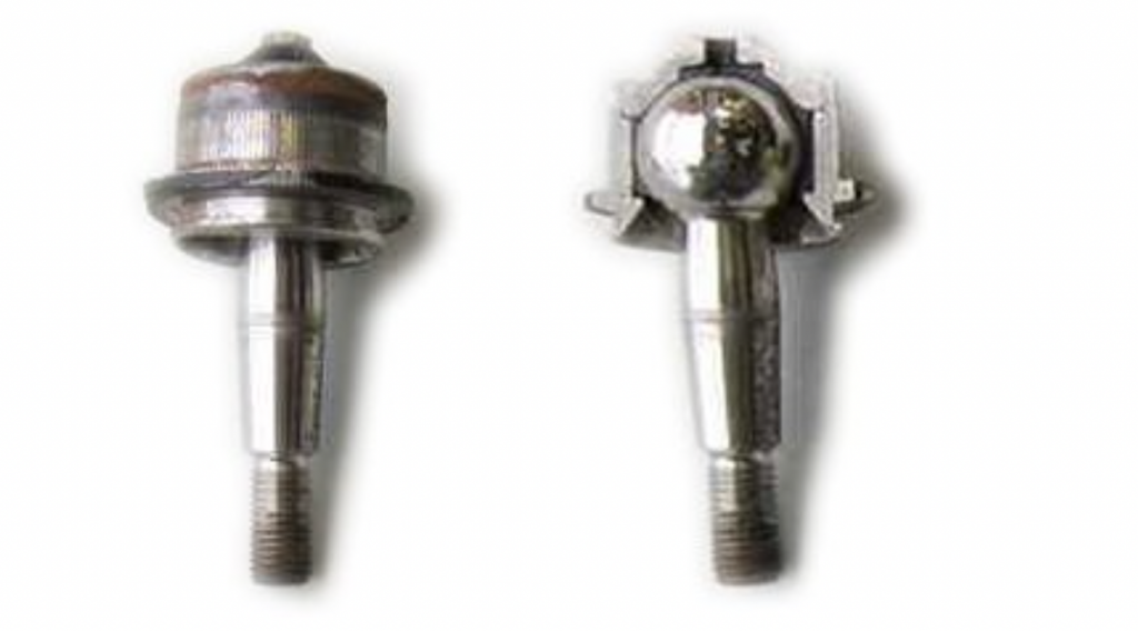
The rod is attached with ball joints in a way that still allows the object to move (sideways and up and down) and rotate normally. The image below shows how a ball joint works — it basically fixes one end of the “rod” (i.e. prevents it from pulling out, pushing in, or moving sideways) but lets it rotate.
As you can see, our object can still move in all directions except it cannot move in the X, or longitudinal, direction, because the other end of the rod restricts the motion by being in tension or compression. We have successfully removed, or “constrained,” one of the six degrees of freedom.
Let’s constrain motion in a different direction:

In this case we have stopped the motion in the Y, or lateral, direction as well as in the X direction but the object can still move up and down and rotate in any of the three directions (ball joints allow for this motion — these are not rods fixed or welded to a wall and to our object). Now, let’s do it a third time:

In this case, what we have done is add a third link just below the first link. By doing this we are still only holding the object in the longitudinal and lateral directions, but we have now stopped it from rotating in the pitch direction (as you can imagine, if the nose tried going up, the bottom link would be in tension and the top in compression; if the nose tried diving, the top link would want to go into tension and the bottom into compression). We have again removed, or “constrained,” another of the six degrees of freedom. Notice that every time we add a link, we remove a degree of freedom.
Since we have six degrees of freedom, if we were to add a total of six links, we could completely hold the object in place and prevent all motion. But that is not what we want for our knuckle. When all is said and done, we still want our knuckle to be able to move up and down so the wheels and tires can go over bumps and through potholes. This means we need to add a total of five links so that there is one degree of freedom left over, and we need to arrange the links in such a way that the remaining degree of freedom is in the vertical direction. Perhaps something like this:

Links 1 and 2 work together to stop motion in the longitudinal direction (X) and rotation in the pitch direction (i.e the object’s nose can’t go up or down), links 3 and 4 work together to stop motion in the lateral direction (Y) and rotation in the roll direction (the object can’t spin around the X-axis), and link 5 works with links 1 and 2 to stop rotation in the yaw direction (if the object tried yawing to the right — i.e. pointing its nose to the right — link 5 would want to go into tension; if it tried to yaw left, 5 would go into compression). All that is left is motion in the vertical direction. Because of the ball joints allowing the links to swing, the object is still free to move up and down. But only up and down.
This is the way a suspension works in its most fundamental sense, and every suspension, with few exceptions, can be described as a combination of five links. (I’ll mention the exceptions later in the article).
(Note on the diagram above: We added the protrusion as part of the capsule because if we attached the 5th rod to the back of the capsule, but farther to the right (in the -Y direction), the links would have crossed and it would have been hard to understand. So this long white protrusion is just something far away from rods 1 and 2 for our 5th constraining rod to grab onto).
It may be tempting here to think that the steering system represents another degree of freedom and that a front suspension must therefore have two degrees of freedom in order to steer as well as move up and down, but this is not the case. Think of the steering system as the “wall” that holds that 5th link. It can hold the link in any position but it still “holds” it in the same way as the wall does. It’s just a wall that can change position. Another way to think of it is that a front suspension is not free to steer by itself (i.e. without driver input) but it IS free to move up and down by itself.
You may now be wondering if I’ve lost my mind saying every suspension can be described as a combination of five links. After all, there are many examples of suspensions that have far fewer than five parts. A MacPherson strut only has a lower arm and a steering tie rod holding the knuckle. A double wishbone only has two arms and a tie rod. Where are the other links? Let’s look at both of these in detail to show how there are in fact five links in both designs.
Double Wishbone
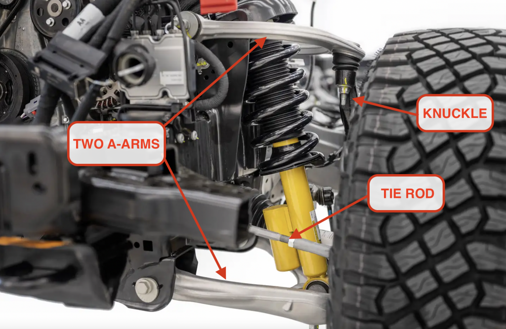
The double wishbone design is one of the most popular suspension designs and has been in use for many decades. It includes an upper and a lower wishbone, or A-arm, and a tie rod (which is connected to the steering rack).
While it looks like there are only three links in this design (two wishbones and a tie rod), each of the wishbones can actually be thought of as two links that connect to the knuckle in the same place. Like this:
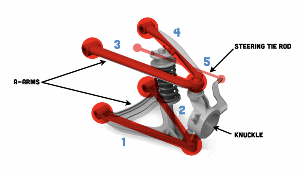
In this way, the upper and lower wishbones are actually four links with the tie rod becoming the fifth.
MacPherson Strut
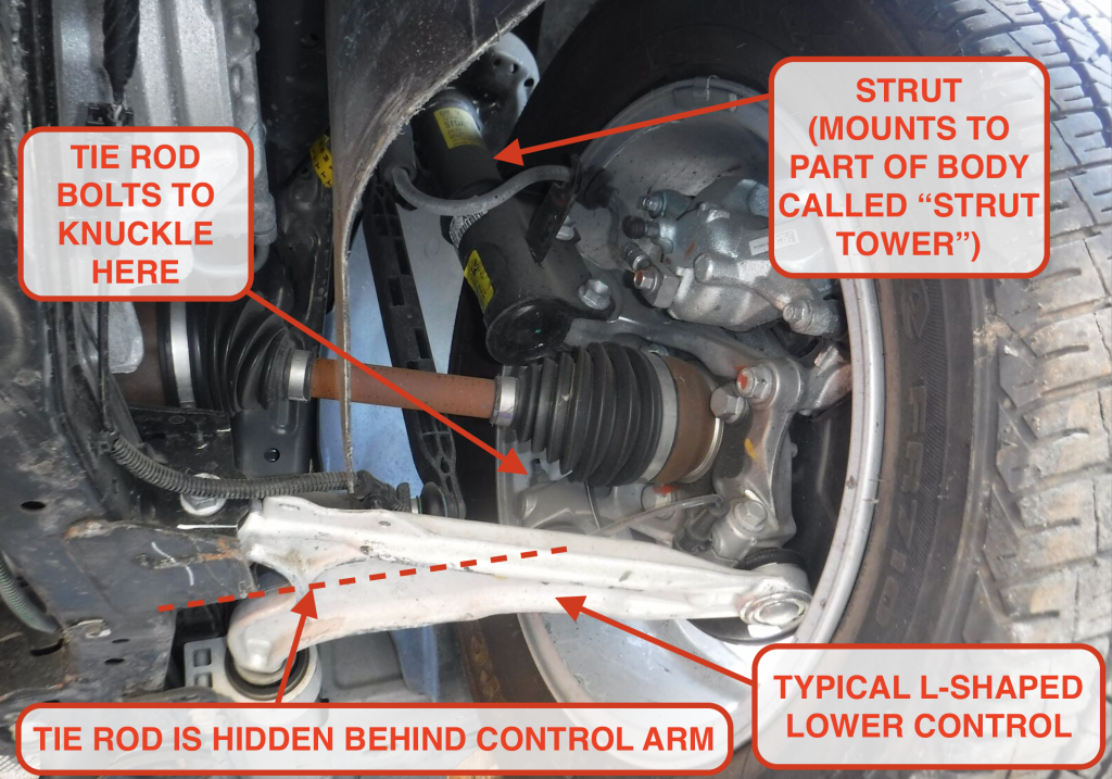
This one is a little trickier — it may look like just three links: the lower arm, the tie rod, and the strut. Maybe four if we treat that lower arm like two links as we did before. But don’t let that sliding joint created by the damper/shock fool you; a MacPherson Strut suspension can still be thought of as a 5-link. Here it is:

This looks very similar to the links in the double wishbone with the exception that the upper links are infinitely long. (Of course, that would be impossible to actually build, but we are only talking about it theoretically here anyway, and I only mention the link length because a sliding/telescoping strut yields motion exactly along its axis, whereas technically short links tend to swing motion into an arch. If you model links as infinitely long, then the arc becomes negligible).
[Editor’s note:
The way I think of this is that the strut — right there where it mounts to the knuckle — is constraining the knuckle in the same way that two links would. It’s not letting the knuckle rotate inboard/outboard towards/away from the car or backwards/forwards towards the front/rear of the car. The strut itself, which mounts to the car at the top bearing, can be thought of as rigid. It’s almost like a rigid, rotating and telescoping pole that the knuckle bolts to. Of course, it’s not actually rigid in real life, as Huibert clarifies:
Yes, they are considered rigid. They are not, of course, and a good dynamics model will include that stiffness but for our purposes it is considered rigid. Just like all the other links. The only non-rigidity we would take into consideration are the bushings.
-DT]
In other words, from a degrees of freedom standpoint, infinitely long links constrain the knuckle in the same way as a sliding joint does. Here again, the tie rod forms the fifth link.
Now That We’ve Constrained The System To Only Move Vertically, Let’s Control The Motion
So now that we have successfully constrained the motion of the knuckle, we still have to hold it in place vertically or else the car would just flop down on the ground. This is where the spring and the damper come in. The spring and damper make sure that the knuckle doesn’t just move randomly along its remaining degree of freedom; that the suspension is able to hold up the weight of the car; and that the car doesn’t bounce down the road like a pogo stick. (We’ll talk more about dampers in my next article).
Exceptions To The Five-Link Rule
Okay, I didn’t want to muddy the water earlier, but for those of you who are ready to dive into the deep end a little, let’s do this. A common exception to the five-link rule is the suspension for a solid axle. The same principles apply, though. A solid axle — which is a singular, rigid object — connects to two wheels, and each wheel needs to be able to move up and down, so we need two degrees of freedom remaining when we get done constraining the axle (one so the axle can go up and down, one so that it can rotate about the X-axis during articulation events to allow each wheel to do its thing). For this reason, the fundamental solid axle suspension is a “4 link.” Each of the four links constrains a degree of freedom, leaving us with two.
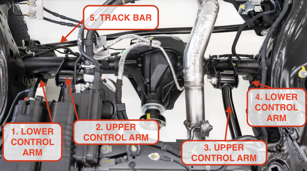
[Editor’s note: I asked Huibert about his claim that a “fundamental solid axle suspension is a ‘4 link'” since I know for a fact that all solid axle Jeeps from the past 20 years have two upper control arms, two lower, and a track bar — that’s five links. The new Bronco’s rear axle also has those five links:
What it comes down to is that the track bar is really only needed because rubber bushings in the four control arms (the bushings are needed over ball joints as a way to keep the ride from being too harsh) have slop in them, and even then, some vehicles have no track bar at all and literally just four links.
Then our conversation went down a rabbit hole, so let’s get into that discussion with Huibert:
Me: Aren’t there five links in a solid axle? Two upper, two lower, track bar?
Huibert:
Yes, that is true but the only reason for a track bar is because the suspension has bushings. The track bar only works because of bushing deflection. Otherwise it would lock up. If you had no bushings, you would not need a track bar.[…]If you replaced the bushings in that car with ball joints, it would only move up and down and rotate in rearview, it would not be able to move side to side.
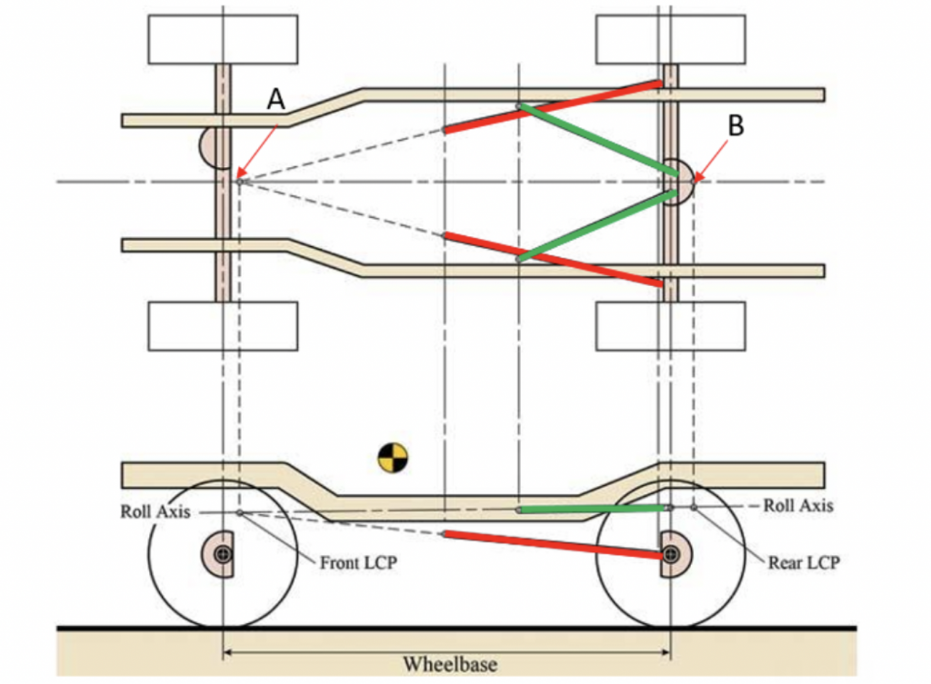
Huibert:The fact that the links are at different angles means they would all be trying to rotate the axle in different directions as they move side to side. This keeps the axle only moving vertically. If the links were all parallel, then it could move side to side. Four links in parallel don’t remove four degrees of freedom since the fourth link is really just redundant with the third one. But put them at different angles and they will remove four degrees of freedom. The axle will be able to move up and down (in a straight line as long as the links are symmetrically arranged) and will allow the axle to rotate in the rear view. A track bar on the other hand moves in an arc since it is attached to the body at one end. This motion would fight with the straight up and down movement the four bars create. Mathematically this would lock the axle in place.[…]It’s actually more about parallelograms. The two lower links form a parallelogram with the axle and the two upper links for another opposing parallelogram with the axle. They work in conjunction to keep the axle centered side to side.
Huibert: The red links form a parallelogram with the axle and the green links create a second parallelogram. If the axle were to move side to side, the red parallelogram would want to make the axle rotate about point A while the green parallelogram would make it want to rotate about point B. The fight between these two parallelograms is what keeps the axle located side to side.
Me: It makes me wonder: Why the track bars on pretty much all coil-sprung solid axles? Are they heavier duty?
Huibert:
No, it is because you need bushings in the links to make the car comfortable and quiet. These same bushings also allow more side to side deflections of the axle and a track bar is a great way to reduce this without adding noise or harshness.. A Watts link is another way to do it without forcing the axle to follow an arc but it is much more complex. Track bars are simple and cheap. Their other downside is that they behave differently in a left vs. right corner. In one they are in compression and want to “flip” the axle over, while in the other they are in tension and just want to stay horizontal.
]
The other exceptions to the rule are some trailing blade and twistbeam suspensions, which seem like they’re overconstrained and shouldn’t move, but that rely on “links” actually deforming. In the case of the trailing blade, designs that bolt the trailing blade directly to the knuckle, such as in the Ford Escape or Focus, actually remove six degrees of freedom from the knuckle and are therefore said to be “over-constrained.” Theoretically this suspension would not be able to move at all. In the case of the twistbeam, since it holds both rear wheels, it should have two degrees of freedom (up and down motion and rotation about the X during articulation events) but instead it only has one: it can only move up and down. In both cases, in order for the suspension to move as it should, some part of the suspension has to elastically deform. (In the case of the trailing blade, it is the blade itself and some of the rubber bushings. In the case of the twistbeam, it is the metal of the beam that bends, or “twists”, and allows the wheels to move up and down on their own).
This sounds bad but it is all very well controlled by the way the parts are designed and the end result is still motion of the knuckle that happens exactly as the suspension designer intended.]
Summary
Okay, now that we’re back from that rabbit hole, a quick summary: The job of the suspension is to control the motion of the knuckle, and it does this by selectively removing degrees of freedom from the knuckle so that the only one that is left is the ability to move vertically. The spring and damper make sure that this remaining motion is well controlled and can hold up the weight of the car. Together, a smart blend of these considerations make sure the wheels and tires point in the direction the driver wants and provide the comfort, ride, and handling the engineers and designers intended.


.jpg)
Great article!
I realize 4-link design could be a separate series all on its own. I’m not sure I completely agree with the comment that the trackbar is only needed because of the bushings. I would assume its more that they don’t have the space envelope in the center of the vehicle to triangulate the upper links. Typically you need at least 15 degrees of triangulation to get a 4 link setup to work without a trackbar. Side to side loads get amplified a lot with shallow angles.
I like this series but would it be better if it was linked to aftermarket modifications at the end of the article? Kind of like these are the design considerations and why the OEM designs it this way. Then go into now that you understand this, here is what happens when you change these items. For example it could have been a good time to explain control arm angles and why when you lift a truck (solid axle or independent) the ride quality goes to shit. Maybe that a takes a fundamental understanding of statics to even grasp. I don’t know, just a thought. Its difficult to write to a broad audience.
Thank you, thank you, thank you for walking away from Jalopnik and setting up this site. The things I know about cars could fill a two-panel marketing pamphlet, but reading well-written articles by knowledgeable people might eventually make me a competent question-asker at the mechanic–and in the meantime will be a great source of new knowledge.
I can’t wait for the article on dampers, I’ve got some broken ones and need to know if it’s worth fixing and how hard it is.
Good stuff, Huibert! I hope you’ll keep going past Suspension 101, cause I’m having trouble visualizing how anti-dive/anti-roll stiffness is built into certain suspensions and whether buying the anti-anti-dive bushing re-locators will actually improve my weekend gravel sessions.
I’m going to mention How To Make Your Car Handle by Fred Puhn again here. FREE pdf download covering basics like roll-center, corner-weighting, bump-steer: well worth the bandwidth to download. (Mind you, I have found myself on EBay after perusing it to look for a Pinto to turn into a Lemons car. You have been warned!)
I’ve always been fascinated by the rear suspension in my GT6. Up front is just a run of the mill equal length double wishbone. But out back it’s got a transverse leaf spring that serves as both spring and upper control arm. The lower control arm is backwards from how you normally see a wishbone (two bushings at the knuckle, one on the frame). Then there’s what’s usually called a “radius arm”, which I think is 1950s British for trailing arm. I think it’s technically a short-long arm configuration with the short arm on the bottom (long-short arm?). I’m not sure if it’s genius for what they had to work with, or just a total abomination.
You’re hitting a great balance of simple enough to be comprehensible to the layperson but complex enough to do justice to the topic. That’s not easy, good job.
First time on the site. First article read.
I think I’m going to like it.
Utterly fascinating, and surprisingly easy to digest. This article has sent me down a Wikipedia rabbit hole of torsion beams, de Dion tubes, and other suspension stuff.
I always enjoyed those kind of explanation articles from Jason and David on and it’s great that you are going in-depth with this this kind of stuff here, while still keeping it easy to understand.
Keep up the good work.
Another great post (even if it made my head hurt a bit).
As an RC car guy, I’d like to see a comparison between full size vehicle suspensions and what my various RC cars use.
This bent my brain just a little bit. I know these are very fundamental concepts of suspension setups; but as a non-engineer, my hat is off to all of the engineers in the room – especially those with the chops to put this stuff into action.
Anyone interested in designing a simple suspension system that could be applied to a riding lawn mower? Huibert?
Basically looking for the best way to go about adding an adjustable suspension to a lawn mower that you could lock in place (for zero suspension travel) when the mower deck is on and you want to use the mower to mow. The suspension could then be unlocked for when it’s in use as a UTV, without the mower deck in place.
Just… not sure where to start.
This sort of content butters my toast.
I am actually working out the final details of increasing the front track width and steering ratio in my 2nd gen MINI Clubman via the usage of 2nd gen MINI Countryman and 1st gen MINI front suspension parts. Might bug Jason and David to see if they’d be interested in running a one-off article about the escapades. 🙂
Another please.
It felt like your target audience was, “Car enthusiast in a pub, slightly tipsy from beers,” and… I mean, frankly, my retirement plan in the dim and distant future is to move into a pub, stay perpetually slightly tipsy and have people tell me interesting things all day long.
I liked that there were practical examples and you’ve gone off and explained them with the theory you laid out, and I’ve come out the other side of this article a fraction smarter and a whole lot handsomer than I was when I started.
That’s a great introduction piece, thanks Huibert!
I can’t wait for you to dive even deeper and finally get me to understand HOW the knuckle is supposed to stay during the wheels motion.
Your job here won’t be done until I’m able to design anti-effects for a homemade chassis on Excel!
Stay tuned!
Interesting. So in this case, would a torsion bar style trailing arm suspension still be considered five link? Or would that be a four link suspension, due to the fact that the knuckle moves slightly in the x axis through it’s travel?
And what of a leaf spring solid axle design? It allows movement in the z direction as well as roll, but it can also have movement in pitch (though that seems more due to insufficient spring force compared to power)?
In order to properly constrain an independent suspension to a single degree of freedom (I disagree with this phrasing as in reality a knuckle in a multilink suspension yaws, pitches, and rolls through its travel in a controlled fashion, but I digress), you always have to have 5 virtual “links”. A trailing arm can almost be thought of as doing the job of two longitudinal links controlling the arc of its motion and three lateral links keeping the wheel end in plane.
In the case of leaf sprung live axles, the fact that they allow some pitch is a bug, due to the low relative stiffness of the springs in that direction. In fact, they often also do not do a good job of constraining lateral motion either due to their length (allows the sprinh to bow in the cross-car direction) and in the case of some vehicles, vertical height (allows the spring to “fold” underneath the car in the cross-car direction).
You are right that knuckles roll yaw and pitch as they move up and down. They do not move perfectly vertical in reality. But, because the rotations of the knuckle are tied to the vertical motion and cannot happen independently, there is still only a single degree of freedom.
I’m disappointed in the lack of De Dion Tube here
a De Dion is just like a solid axle except that the differential is mounted to the body to reduce unsprung mass. From a suspension design standpoint it is exactly the same as a solid axle and would be constrained by a 4 link with an optional track bar or watts linkage.
I’d like to know more about the reasons for going with a trailing blade suspension setup – is it a simplicity/cost savings thing at heart?
I loves me Focus but was initially shocked to hear it doesn’t have a track bar. Then I learned it has a what I think Ford calls controlblade (?) setup and it wasn’t needed. Blew my luddite mind.
I wish there was a diagram of the trailing blade setup, I can’t picture that. Of course, I could Google this, but where’s the fun in that? Gotta keep these guys writing something!
Control Blade was just marketing wank for another form of multilink. Loads of cars have a long trailing link with a pair (or more) of lateral links. In fact loads of side-by-side ATVs have the same sort of rear suspension now as well.
Great article! would you be willing to expand this for some of the funky off road suspensions that are sometimes used? The 3 link is fairly easy to figure out. the 1/4 elliptical suspension is an older design I’ve only ever seen pictures of. Finally there is the “grader ball” suspension, also known as as a one link. To my knowledge no OEM has ever been silly enough to use any of these, they’re all things guys have fabbed together. The 3 link is pretty common though. It is just a triangulated 4-link with one of the upper links removed.
How much does the need for suspension travel factor into constraining axes? For instance, is a trophy truck IRS still considered to just move vertically even though the wheel arcs in two different directions during travel because the alignment between the wheel and the ground remains constant?
The reality is that no suspension moves perfectly up and down. There is always some rotation going on at the same time, just like in a trophy truck. What is important is that the combination of moving up and down while also rotating is completely controlled and constrained. The rotation and the vertical movement are totally “coupled” with each other and cannot happen independently. This is still considered to be only a single degree of freedom.
I did terrible in my dynamics systems class which is probably why I’ll never work in chassis. This article just drove that point even further but great explanation.
Before this article, here’s my complete understanding car suspensions “zero degrees of freedom”…
“Official Pinewood Derby Car Kit”
(4 nails, 4 plastic wheels with hole in middle and a block of wood)
Anything beyond sliding pillar is like spaceflight to me
I think I’m going to just start planning on clocking out for a half hour, driving a couple miles up the road, and sitting down with an overpriced cup off coffee to feed my soul every time I see this Hubert guy make a post. It just makes my day.
Yes, Huibert is freakin’ awesome.
Very well said!
Awe! You really didn’t have to, but thanks guys! You made my day.