
My eBay WWII Jeep project had hit a bit of a snag in our last update. I had cracked a piston, which required me to remove the three piston-rod assemblies I had already installed into the brand new Go-Devil engine block. I then installed three new pistons, only to realize that the fourth piston had a piston ring with a manufacturing defect. Luckily, I found a new ring at an old-school engine shop, and this allowed me to finally get that fourth piston into the France-cast crankcase. But the engine was far from complete.
Installing the fourth piston was straightforward. I clocked its rings so that the gaps weren’t facing the same direction (in order to minimize compression leakage, i.e. blowby), then I compressed the rings with my piston ring compressor, and I hammered the piston top down with a wood hammer-handle.
[Ed Note: If you’ve been following our Instagram page, some of this will be review. We’re a bit behind with the articles, but the full tale of trying to take a WWII Jeep that I assembled in my backyard on an 800 mile journey is coming May 15! -DT].
My Australian friend and wrenching beast Laurence waited down under at the crankshaft to receive the connecting rod, preparing to carefully guide the rod around the crankshaft journal to avoid nicking the crank with the rod bolts.


After I had all four pistons in, it was time to set the crankshaft’s end play; this is the distance the crankshaft can slide axially (in other words, how far it can move from the front of the engine to the back and vice versa as a result of thrust loads). This is a critical measurement because too much endplay can lead to premature failure not just of the engine but also of other components that rely on the engine’s crankshaft (and flywheel) being in the right place (think starter motor, transmission/clutch, etc.).
To understand how to set endplay, check out the image below. Shown here at the front of the motor you can see the front of the first main bearing (this surface is a thrust bearing). Sitting inside that bearing is the front of the crankshaft’s main journal #1. Setting the crankshaft endplay on a WWII Jeep engine basically involves tightening a giant washer against the front of main journal #1, and strategically installing shims under that washer so that the crankshaft becomes offset from the thrust bearing.

The diagram below shows the shims, labeled “R,” as well as the giant washer, “E.” Again, the shims are meant to sit between the front face of the crankshaft’s main journal #1 and the washer, which interfaces with the thrust bearing.
To put it simply, imagine the crankshaft is pulled all the way towards the front of the engine. If the front face of the crankshaft main journal is a bit proud of that front main thrust bearing (and it could be, depending upon how it was manufactured), then tightening the huge washer against the front of the main bearing would still allow the whole crank to move back by whatever distance there is between the front of the main journal face and that thrust bearing.
If, however, that front face of the crankshaft main journal has been properly manufactured such that it’s a bit inset relative to the main thrust bearing, then squeezing that big washer (which you do by squeezing the oil slinger/spacers/washers/timing gear/front pulley/crankshaft nut shown in the diagram) would just try pulling the crankshaft forward, against the inside of the main bearings — there would be zero endplay. The crankshaft would be tight.

Luckily, my crankshaft main journal #1 was far inset, which meant that instead of having too much endplay, I had none — something solvable with shims.
The Go-Devil engine’s endplay spec is 4 to 8 thou (0.004 to 0.008″). Laurence handed me some shims, I chucked them under that washer (which I have in my hand in the image below), and then I installed all that other stuff you see in the diagram (spacers, washers, woodruff keys, an oil slinger, a timing sprocket and a pulley) before tightening the crankshaft nut.

Once that was tightened, I simply pushed and pulled the crankshaft by hand and with a rubber mallet to see how far axially the crankshaft could move, and I read the number on the dial indicator (basically a gauge that tells you how far its plunger has traveled).

Laurence and I did this a few times until we had just the right shim stack under that washer to yield 4.5 thou of endplay. In other words, we added a shimstack whose thickness was 4.5 thou plus however far inset the main journal face was from the thrust bearing when the crank was pulled all the way forward.
Anyway, with endplay all set, we took the pulley off and began buttoning things up.

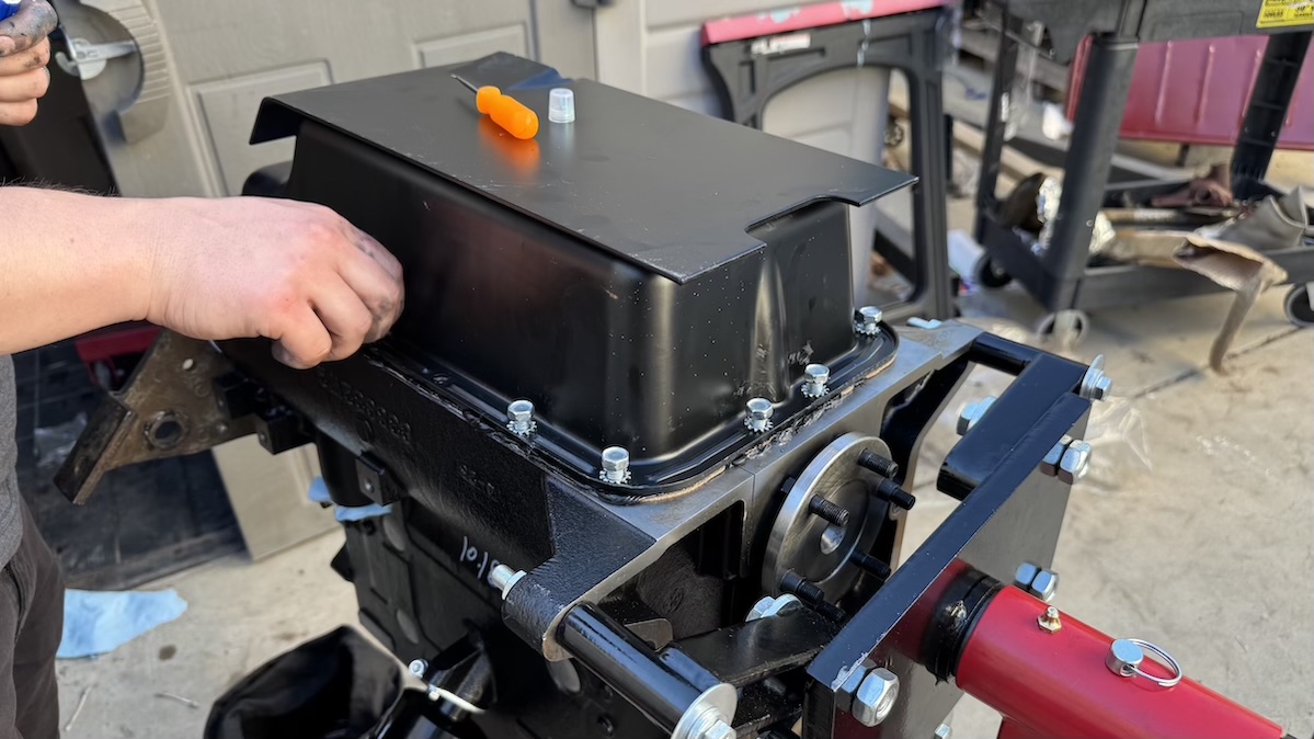
“Buttoning things up” meant installing the “front plate” on the engine. This is a bit of an oddity in that, instead of having engine mounts bolt directly to the engine block casting, the Go-Devil features a large flat plate bolted between the block and the timing cover. This plate has two ears (you can see one on the bottom right of the image above and both are on the left and right side of the image below) that capture the rubber engine mounts that fasten onto the frame.

With the plate on, we set out to get the front timing cover bolted on, but not before installing the timing chain.

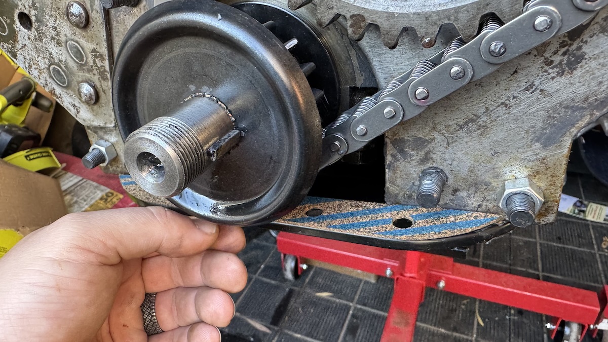
The sprockets that bolt onto the crankshaft and camshaft feature a tiny dot. It’s extremely important that these two dots are facing one another when the timing chain is installed because these dots ensure that the location of the piston (set by the crankshaft) is correctly timed with the location of the valves (set by the camshaft). You can’t just chuck the chain onto the two sprockets because then the piston might be halfway up the bore at the start of the intake valve opening when it should be at top dead center.
Also worth noting: the endplay of the camshaft is limited via that plunger you see in the middle of the sprocket above. Behind the plunger, in the same hole at the end of the camshaft, is a spring, which pushes the plunger against the timing cover that we hadn’t yet installed. This pushes on the cam to give it some axial stability.
Speaking of the timing cover, the image above shows Laurence after a battle to the death with the RTV silicone I had over-used when installing the wrong cover.

Laurence and I had installed the oil pan (which provides the lower gasket for the timing cover), and we’d bolted on the timing cover and pulley, only to realize that the cover was missing a crucial oil hole (it was likely a timing cover for an old 1930s Willys civilian car or a Willys MA WWII Jeep prototype). So we had to take off the cover, cut the oil pan gasket that we’d ruined in the process of cover-removal, and then install the right eBay-sourced cover along with a sliver of cork gasket:
Having to re-do that job was demoralizing, but we moved past it.
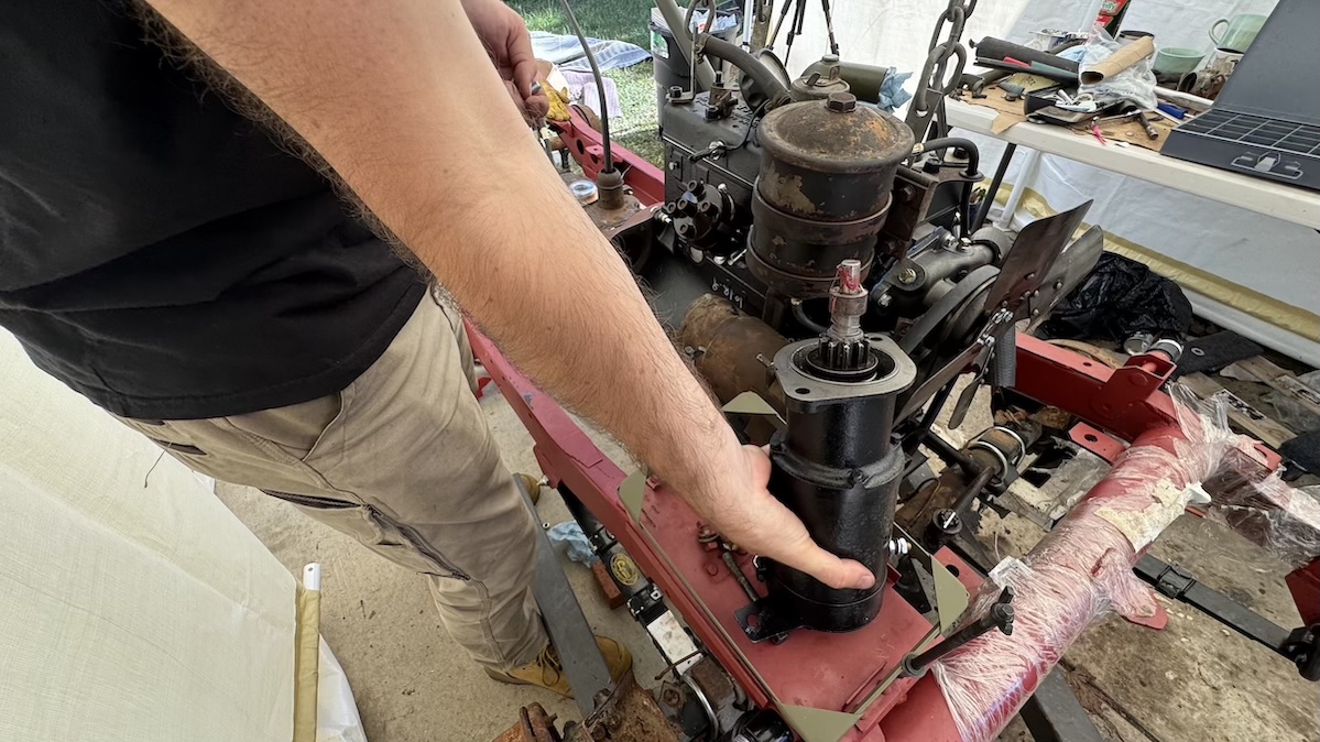
Laurence and I had bolted in the oil pickup tube (shown below), and then we bolted in the oil pump, which you can see on the right side of the block in the image below.

Installing the oil pump was honestly a drag, because we had to install the distributor at the same time since the two mesh with one another, and the distributor has to be rotated just so in order to seat all the way in the block.
The issue is that the distributor will only go all the way if its shaft is lined up exactly with the oil pump shaft. This basically required looking in the distributor hole, seeing how the oil pump was oriented, spinning the distributor shaft, installing it, and praying the thing would finally seat. And it had to seat in the right orientation so that spark plug #1 was at the right location relative to the rotor; this meant turning the oil pump to just the right position, then going ot the other side of the block and lining up the distributor shaft.

It wasn’t fun. But it’s done.

Speaking of components running on the camshaft, I installed the fuel pump via two bolts on the block, and then I started installing the valves from the top of the engine and the valve springs through the side-mounted valve cover. 
The Willys Go-Devil, and many other early, pre-1950s engines, was called an “L-Head” motor, taking its name from the general shape of the intake and exhaust charge as the former enters in through the ports in the side of the block, travels across the engine’s deck, and then down as the piston pulls the intake in.
Then the exhaust goes up and across the deck to the exhaust manifold — both making L-shapes. (Later overhead valve engines were called “F-heads” as the intake charge came in above where the exhaust left).
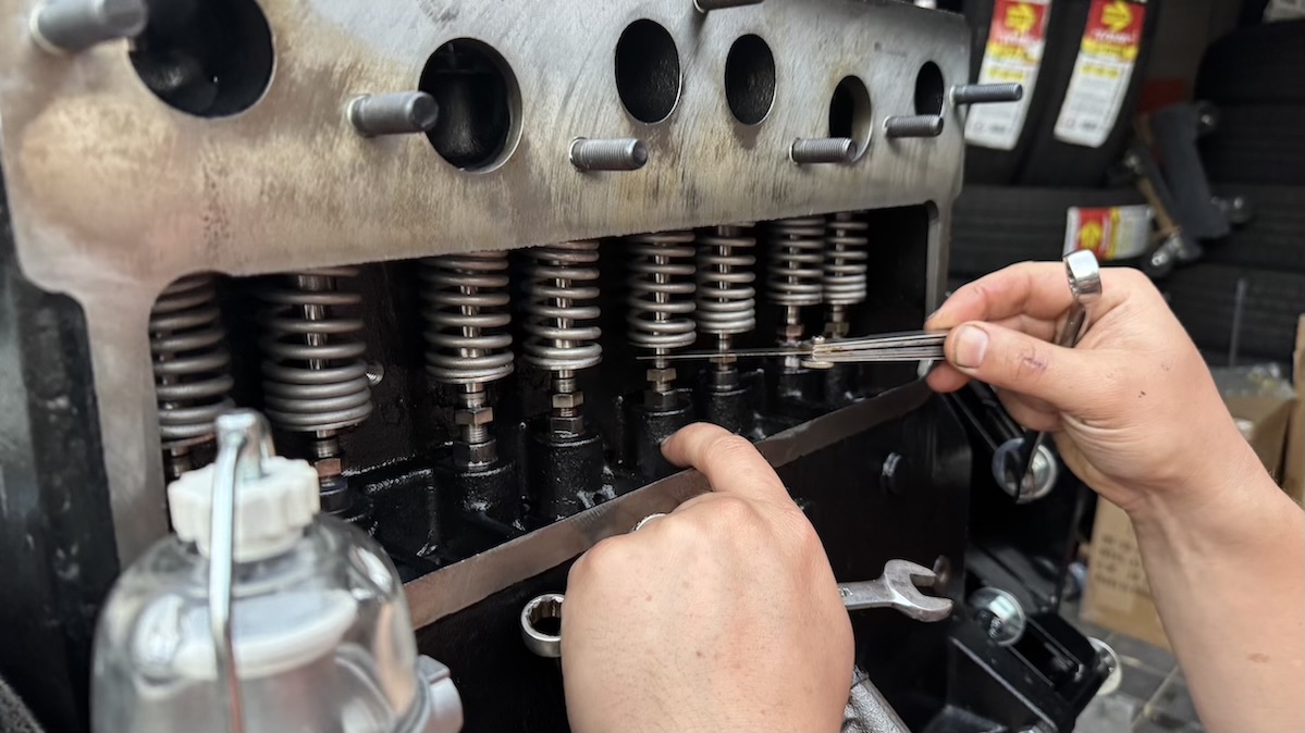
Anyway, the valves being in the block instead of in the head means that all the valve springs and lifters are in the side of the engine. You can see me adjusting it all in the image above.
You can see the valve stems inside those valve springs; the bottom of the valves are connected to a valve spring retainer via little conical things called “keepers,” so that when the bottom of the valve is pushed up by the lifter below, it pushes the retainer, compressing the spring up against the top (the block). The spring is there to make sure the valves close quickly and the lifter down below is making contact with the camshaft lobe.


By adjusting the valves I’m ensuring that, when the engine is rotated to top dead center and the valves are all closed, there is exactly 0.016″ of clearance between the lifter (which rides on the cam lobes) and the bottom of the valve (you can see the gap I’m talking about in the image above). The point is that, when the cam lobe is not activating a given valve, it should still be very close to that valve so that, when that valve gets called into action, things happen quickly and the valves open and close smoothly.
Once I’d adjusted the valves , I installed the cylinder head and torqued it to spec and in the right sequence:


The Go-Devil features a heat-riser system that uses exhaust air to warm up the intake charge; Laurence and I are bolting the intake and exhaust together in the image below.
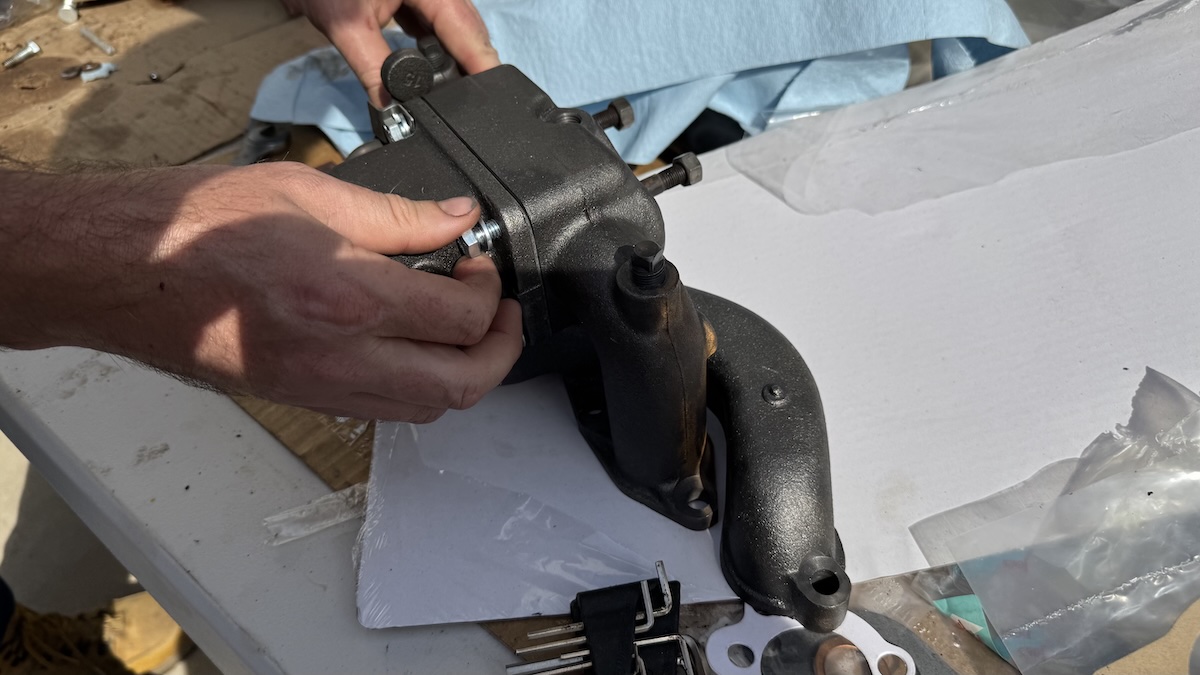
Here I am hooking those manifolds to the motor:

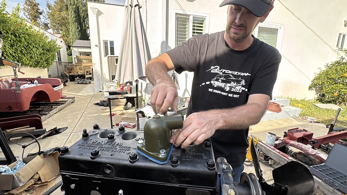
Here’s me bolting up the water pump, which I’d already hooked the new fan up to:

Here’s Laurence installing the three bolts that hold the thermostat housing to the top of the cylinder head:
Here we are installing the dipstick tube we took from the generator engine we bought from that eBay seller in Washington:

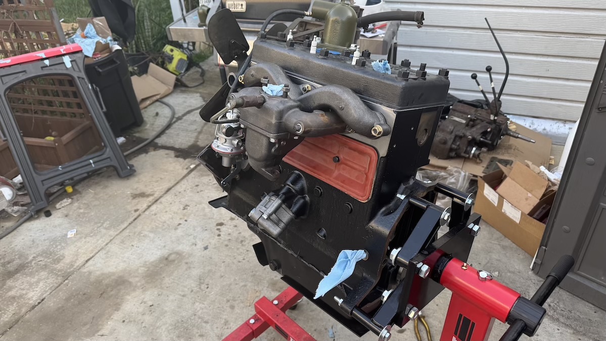
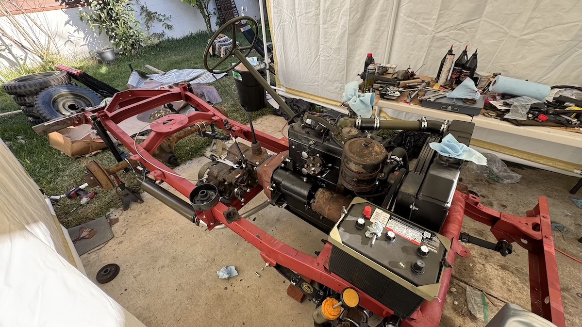
And here is the motor, fully assembled, in all its glory:
This short Instagram reel shows an 80 year-old WWII Jeep engine next to a brand new WWII Jeep engine:
View this post on Instagram
Normally this would all be painted green, but as with the rest of this Jeep, we’ve decided not to paint anything in order to highlight the various parts we purchased from various eBay sellers around the world.
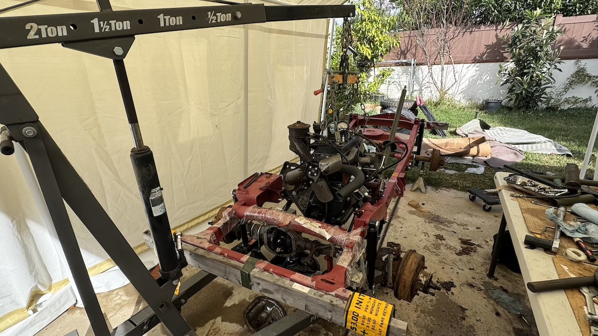
Mounting The Motor To The Frame
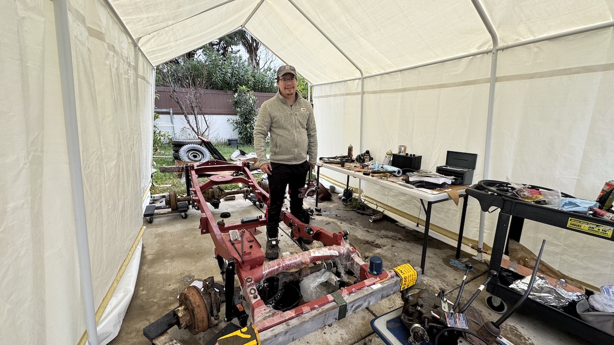
With only just over a month before I had to drive this Jeep — which, as you can see in the image above, was just a bare frame with some axles hooked on — 800 miles from LA to Moab, Utah for the Easter Jeep Safari, Laurence and I knew we had to get this motor up and running as soon as possible.
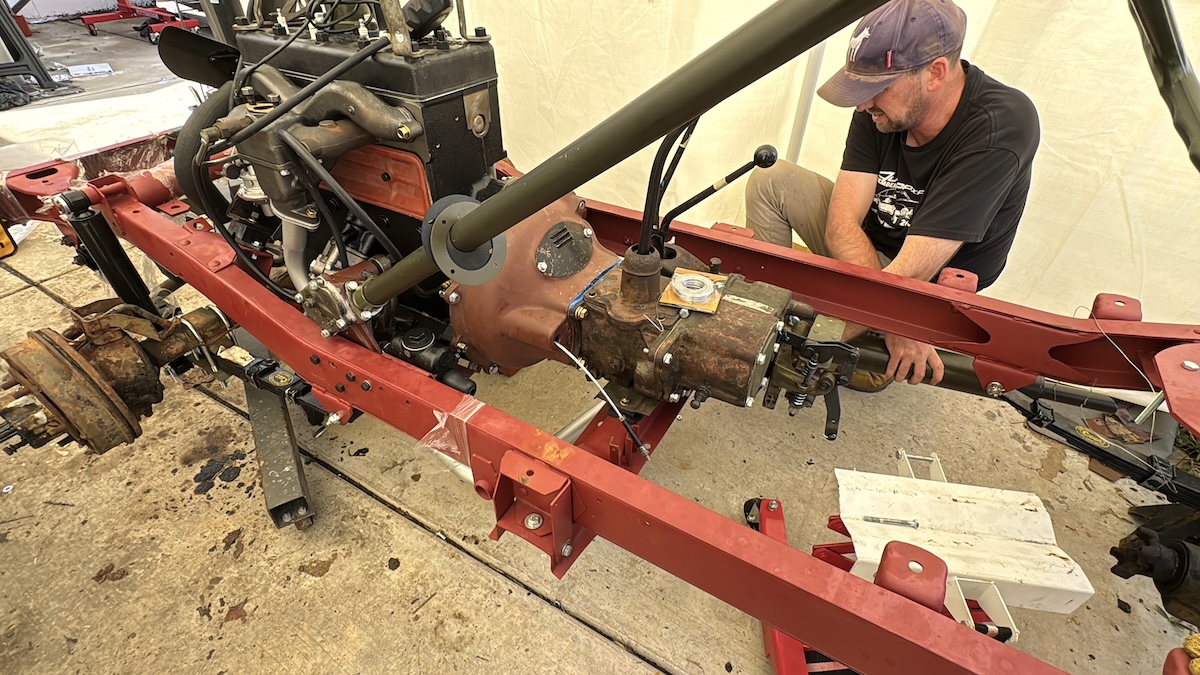
We dropped the engine’s motor mounts onto the frame, loosely bolted them in, and then Laurence and I muscled the transmission and transfer case into place just aft of the engine.
View this post on Instagram
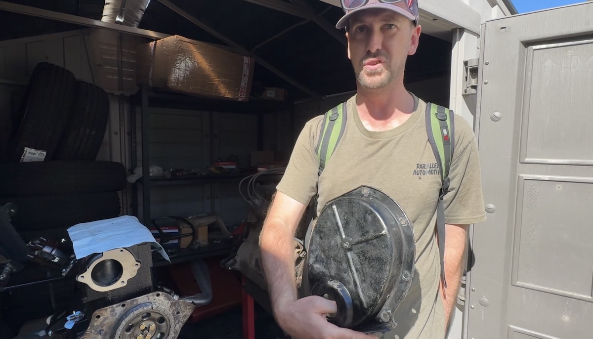
Obviously, you can’t just mate a transmission to an engine without preparing the part that connects the two — the bell housing, shown in the Instagram clip above. This is a wide cast housing that bolts to the back of the engine on one side and to the front of the transmission on the other, and it contains the clutch disc, flywheel, pressure plate, clutch fork, and more.

Speaking of the flywheel, here we are bolting it to the crankshaft:
View this post on Instagram
And here I am installing the clutch onto the flywheel:
View this post on Instagram
The truth is, I’m skipping so much of what actually happened. I’m making it seem like we just went step-by-step and bada-bing bada-boom, we’ve got a newly built engine and a rebuilt transmission mounted to a frame.
It didn’t go like that at all. There was lots of cursing at every single step. There were many long breaks taken to read books and online forums to figure out what the heck we were supposed to do, there was lots of searching for fasteners, and there was just a lot of hammering to get things to line up.
The reality is that building any vehicle from scratch — not simply dismantling something, fixing it, and putting it back together — is a ridiculously hard thing to do. It takes so much research to know which tiny parts and fasteners you need, it takes so much care to make sure you don’t make even a little mistake (I installed my valve springs upside down), and getting parts that have never shared the same system to fit requires lots of grease and brute force.
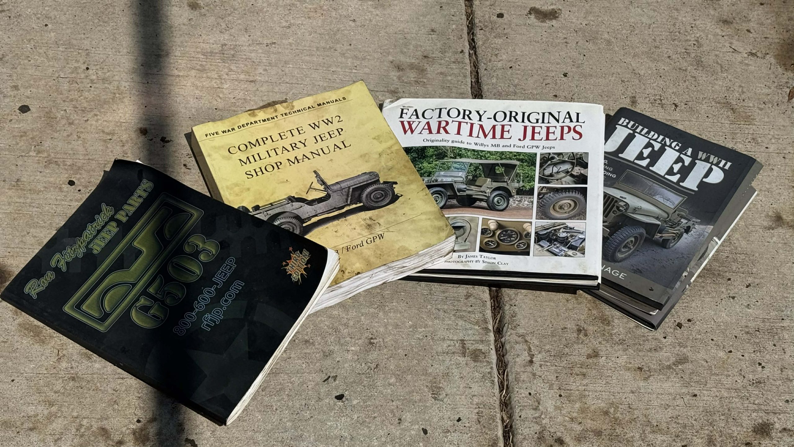
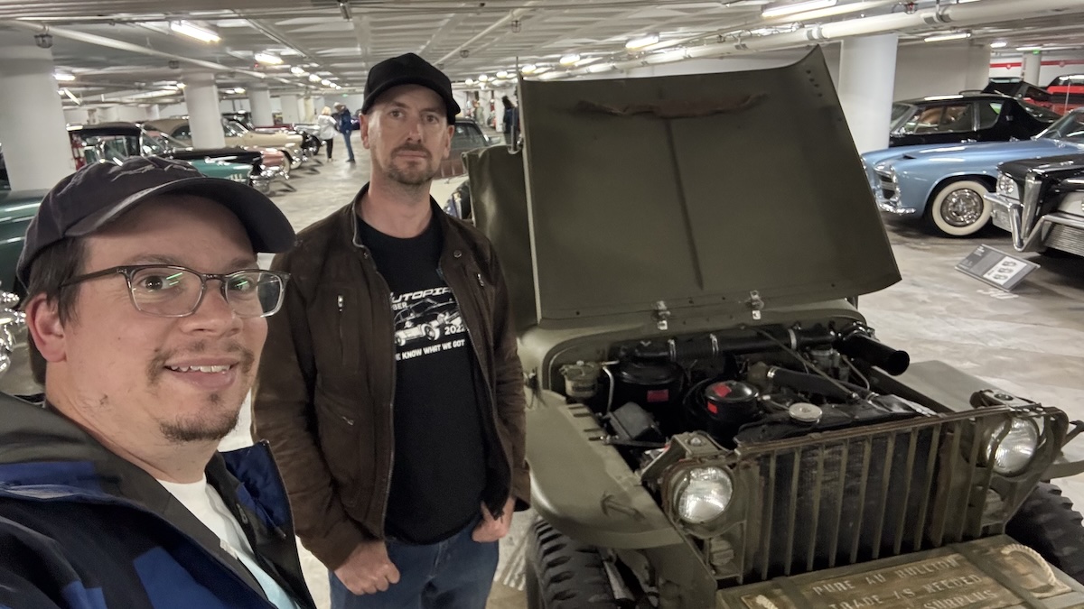
The whole thing is an absurd project that requires me to become a WWII Jeep expert basically overnight. I’ve gladly been reading lots of books to try to get there, and Laurence and I visited the Petersen Automotive Museum to take a million pictures of every nook and cranny to see how this thing is supposed to go together. This is my third visit to the museum for research; thank you Petersen!
Anyway, back to the engine. You can see here we’ve installed the oil filter housing, and Laurence is about to jam the grease-covered nose of that starter motor into the brass bushing that he replaced in the transmission bell housing:
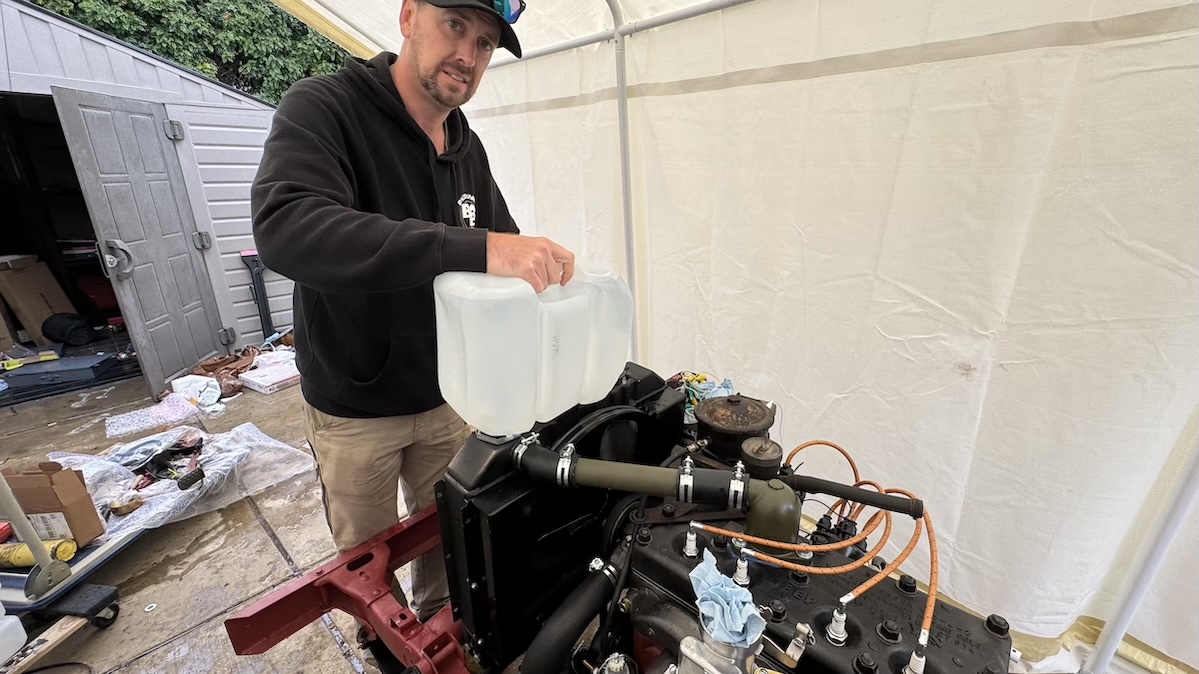
I hooked up the spark plug wires, Laurence bolted up the radiator and filled it with some distilled water, and then it was go-time.
It was time to fire up the motor.
It Runs! Sort Of…
View this post on Instagram
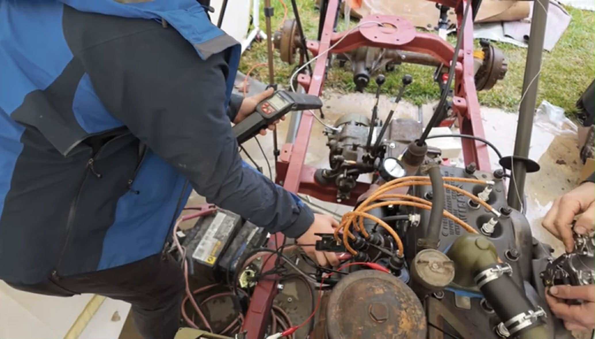
To get the motor to run, I rigged up an ignition system using alligator clips. Battery positive to coil. Coil negative to distributor. Battery negative to ground. That’s it.
Then I ran my jumper cables to the starter motor. Black from the battery negative to the starter motor housing. Red from battery positive to the starter motor’s main stud. Once I hit the stud with the red jumper cable I was expecting to hear the motor turn over, but all I heard was: Click.
Click.
That’s it. Just click.
I hammered the starter motor a bit. Maybe it’s not working properly? Maybe we should have bench-tested it.
Then I hit the starter with the battery cable again. The fan moved! Just a degree or so, but it spun! Was that good news? I’m not so sure. It means the starter is working; is the motor… locked?
Figuring this could just be a super tight motor putting up too much of a fight for a lowly 6-volt battery with thin jumper cables as its main conduits, I ran to my Jeep Comanche and stole its 12-volt battery.
I hooked it up to the jumper cables, then touched the starter post with hot — CRANK CRANK CRANK! There is life!
We primed the fuel pump by hand a bit to fill the carburetor bowl, then sprayed in some starting fluid. BANG BANG! The engine ran a little, then backfired hard! We adjusted ignition timing by spinning the distributor — BANG BANG BANG. Still no dice.
View this post on Instagram
After far too long, I realized I’d swapped two of the spark plug wires. D’oh! With that remedied, we went to crank the motor, only to hear promise. No, we didn’t hear glory like we all hoped, but promise was still a good result:
The engine seems to run; it wouldn’t rev when we gave it throttle, and it definitely wouldn’t idle, but it sounded OK for a few seconds at about 1300 RPM. We didn’t hear any knocks or ticks, there’s clearly enough compression to run… again, it was promising.
Clearly there was something amiss with either the carburetor or the ignition timing or maybe there was a vacuum leak, but the motor’s mechanical bits seemed decent.
Hopefully we didn’t wipe any cam lobes trying to get it to fire up, but I did squirt gobs of assembly lube on those lobes before buttoning up that bottom end, so I’m hopeful.
Hope and Promise are more than I could have said about this project just a month prior, so I’ll take them.


“we’ve decided not to paint anything in order to highlight the various parts we purchased from various eBay sellers around the world.”
We all know that this is an excuse to not deal with paint. I have painted 2 Jeeps, one turned out ok. The other is crap. It turns out I am not meant to do clearcoat in my garage.
OD Green is actually super easy to paint.
I did a single coat enamel in DOT orange on one CJ5 I owned. Got a really nice CJ5 with the Dauntless v6 and under the crappy brown, I found a nice Spruce Tip green paint. I did basecoat/clearcoat on that one and learned that clearcoat is not for the amateur (or at least not this amateur).
It probably doesn’t matter at this point, but shouldn’t that engine be positive ground?
Negative
I love this project. Nice work.
I like the length of The Autopian articles and the detail and the hard work!
However, I’m not sure how to feel that The Autopian is YOUR website, and you’re letting every other site out there (Instagram, YouTubers) get the scoop on YOUR story. It kind of spoils the drama for your articles.
I know that writing is hard and takes time, but it’s frustrating for me have to search other people’s sites and channels for information on an Autopian project.
It’s strange to have to follow follow Instagram to get updates on an Autopian project where I am a member.
And a few weeks ago I saw a YouTube video with you driving this Jeep in Utah and being interviewed about it. It really steals the thunder to already know that you are successful, and it’s frustrating to go back-in-time almost 2 months when reading here.
I’m not sure that there is a solution, The Autopian is a longer, more detailed, thought out format; I like it. But I don’t like having to search other people’s sites and media to get updates on your work.
Social media will always be faster than written stories, and I’ve been writing stories like this for years (my FC project, my Holy Grail ZJ project — I socialed LIVE, then wrote after). I did share some sneak peeks with members in the member email and on Discord, but appreciate the feedback. I’ll be giving plenty more sneak peeks to members, including the overall cost of the project, how I got it legally on the road, how the road trip from LA to Moab went, how things went off-road, etc.
Lots more stories to come on this absurdly challenging Brand New WWII Jeep project!
I understand, I guess I felt a little left out?
I’m a member, I check The Autopian every day, I’ve been a bit anxious and excited for you to get it done!
But even now I would still have no idea that you were actually successful and that you were in Utah, if I hadn’t accidentally run across someone else’s YouTube channel.
It’s a little like a close family member having a big event in their life that you were anxious about for them (big promotion, big vacation, medical procedure, etc.), and you only find out how it turned out a month later from a friend of a friend. It was your decision, but that does say something about our relationship? You didn’t think to tell me?
It’s also my fault for not following Instagram i guess; but I’m not going to. I have moral objections to Facebook/Meta.
I’m being a bit dramatic I guess. By nature of the format, the main Autopian page is probably not the place to expect to get my breaking news on the Autopian writer’s projects. Although even the Autopian YouTube page has no updates last I checked? I’m on the Discord, but rarely check. Are there more updates there?
I did send you an email; every member got the news first!
But I get where you’re coming from; The TFL thing was a great opportunity we had to take to help expand our excellent community to more car nerds.
Then it’s my fault for missing that update!
I recognize I’m being a bit dramatic about it all, and it was nice to see Autopian writers out there getting visibility and recognition!
David, if you have a gasket you usually do not need any silicone – use silicone only if you cannot get a properly cut gasket. If you have a need to position the gasket on one piece to make assembly easier, then use a few drops to hold the gasket in place, although for most applications I would use the Indian Head Gasket Shellac, which is easier to apply and which cures faster. Permatex also has a few other products like gasket dressing that may also work at somewhat higher temperatures.
I alway put a little dab of RTV all the way around my gaskets. Holds them in place, gives me peace of mind; been doing it for years.
While Dave loves his Room Temperature Vulcanising silicone, I’m a Loctite 515 man after being introduced to it by my mate Gordo the tractor mechanic who wired up Project Cactus.
For something you’re not looking to take off ever again, I’m not against a bead of RTV. I definitely don’t use it on something like both sides of the gasket on a valve cover as there’s a good chance that’s coming off again in the near future.
I’ve been following along on Instagram, and I’m thrilled to see the articles as they’re posted. This looks like it’s been a great project, and I’m glad you’re so open about the challenges and frustrations as well as the triumphs.
Thank you!
Way to go Laurence. Wrenching with David probably makes the plane flight from Australia seem easy.(That’s not a wrench!).
Congrats Mr. Tracy.
Thanks mate! Even though it’s a 15hr flight it wasn’t that bad. Probably helped that the plane (A380) wasn’t packed with passengers.
We have a bit of a rhythm when we turn spanners together, even after 3 years it was pretty easy to get back into that again.
Dave has significantly improved his organisation as well, even if the backyard still looked like chaos!
Yeah, Laurence I think this was a bit more organized than Cactus, if only because it kinda had to be. We had real complex stuff we were dealing with — transfer case, engine, steering system. And we weren’t just bolting it together, we were building it all to tolerances within a few thousandth of an inch. Between that and our Hud-less-ness, there just wasn’t any time for spider… uh, handling.
Truly one of my favorite Aussie idioms!
Thanks guys for the reply!!!!
Way to go!
Never did anything remotely as deep-divey as this myself. However I can attest to the utter joy felt when an engine turns over after you’ve put it back together after having taken it apart. It was delightful to witness your joy, here.
Well done, sir.
Laurence seems so comfortable and at ease with both the process and explaining it in front of the camera. Having him there for this must really help both in getting things done, and with the confidence that you’re going to get things done.
He could easily have his own YouTube channel. And I would watch it.
Yeah, having a second pair of competent hands made me not just 2x as productive but more like 4x. Though Laurence hadn’t worked on flatfender Jeeps, Laurence is a walking wrench, so — thanks to YouTube videos from a guy we jokingly called Chad GPT and thanks to great reference books — he was a natural, and those three weeks were a huge boost for the project!
Also, it’s invaluable to have a second, different mind to think about the problems that inevitably come up. Someone to bounce ideas and solutions off of until the right answer becomes apparent, or you decide to hit the damned ball joint with a big effing hammer.
Absolutely!
Thank you, I really appreciate those kind words!
If I had the time, money and a camera person/editor I’d love to do some more video like this but I guess I’ll have to stick to my day job
Such a fun project that I would never undertake so I’m enjoying reading about it.
Jeep! Jeep! Jeep! Jeep! Jeep!
(and I’m not really even a Jeep guy)
This is the content I’m here for! I’ll admit my engine knowledge is limited to much newer stuff, starting with the SBC and moving forward, so seeing the valve cover on the side of the engine, and the valves UPSIDE DOWN and IN THE BLOCK, well they are things I intellectually understood, but I’ve never seen how that works in practice. I probably would have put the valve springs in upside down too, just out of muscle memory.
Great Stuff!
Imagine how L head mechanics felt the first time they saw an OHV engine with their valves and pistons fighting for the same physical space.
I only found out the other week that early Land Rovers had an engine that was half side-valve, half overhead-valve. As in, the intake valves are on top, operated via rockers, and the exhaust in in the side.
I had no idea there was such a layout, but after a bit of reading it seems to have been a common stepping stone between side valve and overhead valve engines.
Same here, but the only engine I’ve ever rebuilt is the one in my air-cooled Beetle. Dead simple, but different than pretty much any water-cooled engine out there.
EPIC.
Rod
Crankshaft
Endplay
Working down under
Backfire, hard
Thrust bearing
I feel like I’m watching a Regular Cars review.
I hope you didn’t tighten the exhaust manifold to intake manifold bolts until after you’ve torqued the manifold to head bolts. torquing them first can result in vacuum and/or exhaust leaks.
Correct. Nice and loose between the manifolds, then tighten them both to the block, then tighten them to one another.
This article has me like a 10 year old opening a Christmas present. There’s just so much neat stuff included here that you never get out of the confines of a paper magazine or a cut-to-length YouTube video.
Bang up job, and thanks for doing this project.
bada-(@#$%^&*)-bing-(@#$%^&*)-bada-(@#$%^&*)--boom
I was *sure* no one was listening !
I saw your MOAB Video on YouTube. Amazing build and far more invloved than my original thoughts. Good on you for doing this, and being fully upfront about the risk.
I don’t know why, but I was expecting photos and videos of Van De Graaff generators, lightning strikes, and a maniacal, white-coated scientist screaming, “It’s alive!” Lawrence does a pretty good – but too handsome – Igor.
Fascinating stuff. Can’t wait for the next installment.
You are 40 years too early. The name is pronounced I-Gor and he was handsome in his mother’s eyes; Walk this way! And Terri Garr’s knockers were awesome.
Damn your eyes!
Too late.
What hump?
The day “ Wall this way “ is no longer funny, just pull the plug: I’m already gone
I wonder if Frankenstein worked on those too.
Did you mean to state worked on those two?
That two.
Haha, thanks! I am adept at flipping levers!
You’re a good sport. Sorry I spelled your name wrong. I should know better, my grandfather spelled his name the same as you.
How do you set the timing if you can’t start the engine? I’ve always used a timing light but that doesn’t work if the engine is not working
You drop the distributor in with the engine at TDC on the #1 cylinder, with the rotor pointing at the #1 plug wire on the distributor cap. That should get you around 0 degrees timing, which is usually close enough to get the engine started. Once it fires, you can dial in some advance and get a timing light on it.
Thank you for the information. Unfortunately I don’t understand it, I assume if I’m I could I would already know the answer. Funny how that works
We did pretty similar to that and set it up statically with #1 piston at TDC from when we installed the timing chain and before we put on the cylinder head while working with the oil pump installation.
There are timing marks on the flywheel of a Go-Devil engine. The distributor also attaches with a slotted end to the oil pump much like a Chrysler small block V8, so you can only ever be 180 degrees out, unlike with a toothed distributor gear like in a Slant or Hemi inline-six.
I don’t set ignition to TDC, I always start at 5 degrees BTDC and go from there as just about every engine from the 40s to the 70s have initial timing somewhere near that and it helps with getting the engine to fire up that first time plus you have more ‘sweep’ available to set up more advance if the engine demands it.
The process sounds pretty similar to the Land Rover engines.
You can use a VOM to set static timing by using timing marks and circuit open/closed. Standard practice on vintage motorcycles.
Same for air-cooled VWs.
Instead of a VOM for static timing I just use a loose spark plug attached to the #1 plug wire and grounded against the engine block, then look for a spark while slowly rotating the distributor back and forth a few degrees. Of course the distributor has to be installed in approximately the right position first, as described above by SoCoFoMoCo.
Well, except on my two-stroke SAAB, for which the designers decided to place the timing marks with reference to the #2 plug instead.
I always do it by eye and 90%+ of the time when I do put a timing light on it, it is dead on. Just line up the desired timing mark and mark on the crank shaft. The rotate the the distributor until the points are right at the point they will open, or in the case of electronic ignition the reluctor lines up with the core of the pickup.