

At the risk of getting overly philosophical, I’d propose that much of life and what we experience in the natural world is energy transfer. I will go one step more specific in arguing that most of engineering as a discipline is about managing energy transfer in one form or another (hint: my pen name here is Zero Entropy). A nuclear plant generates heat that creates steam to drive a turbine. A rocket engine burns fuel that propels it forward. A squirt of gasoline is ignited to drive a piston downward. A lot of these processes, as complex as the engineering involved may be, feel tangible because we can visualize it.
The electric motor, despite its extreme mechanical simplicity and its ubiquity in our lives, I think is more mysterious to the average person. It converts something invisible and silent into something we can feel and often see: torque. It can just as easily reverse that conversion.


In the long overdue part 2 of my demystifying electric vehicles series, we are going to talk about torque — how an electric motor makes it, and how a modern electric vehicle controls it. The first part of this series talked about the performance characteristics of an electric motor and why they are well suited for automotive applications and simple single-speed gear reductions. I recommend taking a read here as its been a while.
When I pitched this idea to David Tracy some many years ago in a bar on Woodward Avenue, my goal was to get a platform to wax poetic about EVs to an enthusiast crowd. I thought that EVs, despite the many extreme performance electric vehicles being produced, were getting a bad rap in the car community, and part of that was due to a lack of appreciation for how they worked. Maybe, with a little work, I can win some hearts and minds.
The challenge here is writing something that everyone from different technical backgrounds can get something from. I was blown away by the quality of questions and comments last time. Autopian readers, you are a technically savvy group. But even if you don’t count yourself amongst the enginerds, stick with me, and I hope you come away with a better understanding of how an EV, or any motor, works.
Internal Permanent Magnet Motor: A Combination Motor That Combines Permanent Magnet Motor Torque With Something Called Reluctance Torque
The most common type of motor in the automotive world is “internal permanent magnet” or “interior permanent magnet” type, or IPM. As you may guess, in this motor the magnets are on the inside of the rotor. That matters, as we will get to later. All IPMs fall under the synchronous type of motor. This means that the frequency of the AC current flowing into the motor exactly matches the motor speed. Perhaps in a future article we can dive into the different types, including asynchronous (induction) motors, but know for now that the characteristics and mechanisms by which they work are similar.
The cool thing about an IPM is that it actually combines the mechanisms of two different types of motors in one: permanent magnet and reluctance type. I am going to drop this equation here that describes how current, flux linkage, and inductance make torque in an IPM driven by something called “field oriented control” (FOC). I don’t expect any of it will make sense by looking at it, but we will break it down step by step and the physics of each part.

Simple as that, right?! Torque equals some letters – one of them being Greek!
Let’s start at the beginning to simplify this. The first term, (3/2)PP is not that important to understanding how this works (phew!). The (3/2) is there as a result of some math converting 3 phase AC currents to our DC equivalents, and the Ppterm stands for pole pairs.
Think of motor pole pairs as the number of north-south magnetic poles in the rotor. A motor with a single pole pair has two magnetic poles, a north and a south. In a complete 360-degree rotation, the motor has gone through one complete magnetic cycle. The motor will go through as many electrical and magnetic cycles per mechanical revolution as there are pole pairs.

Permanet Magnet Torque
Now let’s get onto the meat and potatoes part of what makes torque.

The rotor’s permanent magnets create a magnetic field, while current flowing through the stator creates another. When we control the stator current so that its magnetic field is oriented appropriately relative to the rotor’s magnetic field, the two fields interact and produce force.
Looking at the torque equation from before, ???? (lambda) is the flux linkage of the permanent magnets in the rotor. Some people may refer to this component as the “permanent magnet” part of the torque equation.

First, what is magnetic flux and flux linkage? Magnetic flux is the amount of magnetic field that is passing through a defined area or 2D loop — for example, a loop of wire. The greater the magnet field strength, or the greater the area looping that field, the more flux you have.
Flux linkage is similar, but a more useful engineering term, because usually we have multiple loops of wire in a coil that the flux passes through, not just one. The flux linkage is the total coupling of that flux, taking into account the multiplying effect of those loops.
So how does this make torque? It has to do with something called the Lorentz force law, which states that a current-carrying conductor in a magnetic field experiences a force. Freshman physics courses teach the “right hand rule” to describe the orientation of the force relative to current and field vectors:
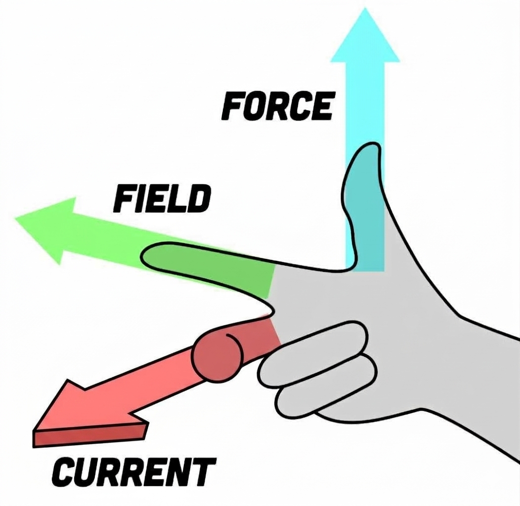
When current is flowing 90 degrees (this orientation is indicated by the subscript “q” in the current “iq” in the torque equation) with respect to the magnetic field, a force is produced between the two. This is torque! At first glance, this equation may raise an eyebrow. Mathematically, how can flux times current give torque? Interestingly, the units of flux (Webers) multiplied by current (amps) equals joules. One joule, a unit of energy, has the same base dimensional units as a newton-meter… the unit of torque we are familiar with!
Reluctance Torque
The magnets get all the glory, but the Internal Permanent Magnet motor has a second way it can make torque. Reluctance does almost as much heavy lifting as the PM flux linkage component, but the mechanism by which it makes torque is different. It comes from a piece of ferromagnetic material (like steel rotor laminations) wanting to line up so that magnetic flux flows in the path of least resistance — or least reluctance.
[Writer’s note: Before I get into that, a short rant: Back in 2017, when Tesla launched the Model 3, some reviewers and over-eager fan boys raved about the new technology of what they called “Internal Permanent Magnet Synchronous Reluctance Motor” or IPM-SynRM. This garnered a collective eye roll from some of my colleagues in the industry, because it was actually nothing new. Every IPM motor has a component of reluctance torque, and the industry had used IPM for many years, long before the Model 3 came along. I am not aware of Tesla actually using that term, but it’s been popularized enough on forums and by YouTube authority figures to catch on and persist. Just know that the IPM is the most common type of primary drive motor in the last 10+ years and we are talking about the same thing. -ZE]
To understand magnetic reluctance, it’s helpful to make it analogous to an electrical concept many people are more familiar with: Ohm’s law. Ohm’s law states that voltage equals the product of current and resistance, or V = I*R. You can draw a simple circuit with a voltage source, like a battery, and a resistor. The lower the resistance, the more current flows through the circuit for a given voltage.
In this analogy about electric vehicles, magnetic reluctance is comparable to resistance, flux to current, and something called “magnetomotive force,” or MMF for short, is comparable to voltage. Simply put, reluctance is the opposition to magnetic flux in a material, just like resistance is in Ohm’s law. Higher MMF drives greater flux through the magnetic circuit, just as higher voltage potential drives more current for a given resistance.

Air has extremely high magnetic reluctance compared with electrical steel. Electrical steel has a much higher magnetic permeability, making it a much easier path for magnetic flux. As you might imagine, low reluctance is generally a good thing in an electric motor. Much like water flowing down a river, magnetic flux wants to follow the path of least resistance (reluctance). The interesting bit is that if the rotor of our electric machine can change its orientation to provide an easier path for the flux, it will experience a force aligning to that.
This phenomena can be used to our advantage. By designing the rotor cross section with radial paths of low and high reluctance, we can create a second mechanism of torque. The rotor will try to align itself to the path of least reluctance. This is reluctance torque.

“Saliency”
The second part of the torque equation from earlier describes reluctance torque:

You’ll notice that there are no terms here for reluctance, rather Ld and Lq appear instead. This is the inductance of the motor in the d and q axis.
Inductance is the electrical property that resists changes in current. It also describes the characteristic of a conductor to store energy in a magnetic field. Inductance is inversely related to reluctance, so with a little substitution we could put those R terms here if we wanted to make the reluctance origin more obvious.
The d and q subscripts describe the angle about the motor’s axial position. A future article will dive much deeper into what this means and how it is controlled, but for now know that the d and q terms are 90 electrical degrees rotated from one another.
Thus, the reluctance torque is equal to the current (id*iq) multiplied by the difference in inductance (Ld-Lq) between the d and q axis. Whether we describe it in terms of reluctance or inductance, we’re seeing the same underlying physical phenomenon: the rotor presents different magnetic paths depending on its orientation. The fancy engineering word for this is saliency. When a rotor has saliency, it means there is a difference in the inductance between the d and q axis. That difference is what makes torque.

Why Internal Permanent Magnet Motors Are So Popular
As mentioned at the beginning of this article, the IPM is a combination motor. It combines the mechanisms of a permanent magnet machine with reluctance torque from saliency. Before we get into what this looks like, let’s talk about why. Why not just have a much simpler design? One with just permanent magnets, or perhaps forget the permanent magnets altogether and drive our EVs with switched reluctance motors?
With anything in automotive, it comes down to a trade-off of cost and performance. Rare earth magnets are expensive and have been the subject of geopolitical turmoil as of recent. Automakers are wise to minimize their content in a mass-production vehicle.
This has driven some automakers to try to avoid permanent magnets altogether. Take BMW, for instance; they switched to an old-school separately excited motor with brushes, all to eliminate any dependence on fluctuating magnet prices and availability. The rotor is its own electromagnet, powered by a separate electrical circuit forming the field.

Other automakers utilize induction motors, which also have no permanent magnets. This is especially appealing as a secondary motor on an AWD car. That is, one that isn’t energized constantly and only comes on periodically.
But none of these alternatives offer the raw performance of the permanent magnet motor, either in torque and power density or efficiency. Consider that you may save some money on magnets, but if that costs you efficiency, you now need more battery to get the desired range. How much does that extra battery cost? How much weight is added? The calculus here is complicated, and it is valid that each automaker may come to a different conclusion about what fits their needs best based on volume, performance, cost, and availability.
The IPM motor is designed to maximize the benefits of permanent magnets, while minimizing the amount of magnet material used. The magnets are placed on the interior of the rotor cross section, typically in a V or even double V arrangement. There may even be carefully designed voids of air stamped into the cross section. These features are there to create flux paths that drive saliency and reluctance torque. If the magnets were placed on the outside of the rotor, as they are for a surface permanent magnet motor, there is no saliency, and thus no reluctance torque.
Designers carefully trade off magnet material and cost to lean more heavily on the reluctance torque component. It’s a complicated optimization problem balancing multiple attributes!

I think in a lot of people’s heads, the electric motor propelling their EV (or E-bike, scooter, train, lawnmower…) is a black box they rarely think about. The fact it operates silently and generally without any commotion reinforces this. It is not shouting for attention like your project car with an exhaust leak.
I hope I’ve added some visuals to what goes on in that energy conversion black box. When boiled down, the most common type of motor in modern EVs operates on a combination of two fairly simple [Ed Note: If you’re an enginerd. -DT] physical phenomena.
This has all set up the next planned installment in this series where we talk about control. How does the inverter convert DC power from the battery into AC three-phase currents? What was I talking about with the d and q axis here? How does the car so precisely and smoothly control the amount of torque the motor is making? And finally, how does regenerative braking make energy flow the opposite way?
If I haven’t bored you to death and you made it this far, I hope you’ll join for that! In the meantime, I’ll do my best to answer questions in the comments.
Top graphic images: Tesla; The Autopian


My background is electrical engineering. You did an excellent job explaining a complex topic in an easy-to-understand way.
Thanks, Vinny! Stay tuned for the next installment.
I’m surprised more people aren’t entranced by the sheer simplicity of an electric motor, you essentially have a bunch of iron and copper on a stick, and it’s powerful and versatile enough to propel 99% of vehicles without stupidly complex transmissions.
Same with efficiency, I still find it hard to believe that my series hybrid, with its multiple stages of energy conversion (engine – gen motor – gen inverter – HVDC bus – traction inverter – traction motor – wheels), can match and even beat a directly coupled ICE and transmission below highway speeds.
Agreed.
Series hybrid is an elegant solution, but there is a reason the series/parallel setup used by many automakers is so popular. That parallel arrangement can be more economical for the reason you state: fewer energy conversions.
Thank you, this dragged me back to my physics and EE courses from so long ago. I thought all this stuff was in some diary storage cabinet in the back of my brain, but came cheerfully shambling out to say hi!
Thanks for the feedback. I’ll try to get next installment in the coming month or so.
A month, a year, when you can get to it. Really enjoy the deep tech articles.
“In this household we obey the laws of thermal dynamics!”
Did you have to put up that right hand rule illustration? I’m having flashbacks to my electricity/ magnetism physics class. The professor had it in for me, as I may or may not have made a slightly out loud disparaging remark about his wife.
Careful what neighborhoods you flash that symbol!
Very interested in this. In my mind, reluctance torque specifically would be very spiky.
It is! In most circumstances, you inject some “wrong current” into the motor to slightly counteract these peaks. The motors almost always have high resolution encoders that map their rotor positions down to tiny fractions of a degree of rotation, so the inverter knows, where in one rotation cycle, the motor is.
(It knows this because it knows where the motor isn’t)
(By subtracting where the motor is from where it isn’t…….)
A lot of cheaper ebike hub motors (especially Chinese ones, with magnets mounted on the rotor/hub’s inner surface) make do with three Hall sensors, NIU is slowly moving to encoder-based hub motors on their pricier bikes though.
I’ve even come across some cheapo ebike controllers with a fallback feature: if one of the Hall sensors dies, it goes into a janky sensorless mode (probably six-step commutation like an RC plane motor). It hums like crazy if you twist the throttle at standstill, give the bike a push though and it will start accelerating, just quite jerkily
Torque ripple is a challenge for many types of motors, especially at low vehicle speeds.
For a 3 phase machine, the 6th order ripple (6 times the motor speed) is the main one.
As Chorls mentions, there are some compensation techniques to attempt to cancel these.
Or you just leave them and enjoy the mrrrrrrrrrrrrrrrrrrrrrrrrrrrrrrrrrwhooooooooooooooooooooooeeeeeeeeeeeeeeeeeeeeeeeeeeeeeeeeeeeeeeiiiiiiiiiiiiiiiiiiiiiiiiiiiiiiiiiiiiiiiiiiiiiiiiiiiiiiiiiiiiiiiiiii sound your vehicle makes with completely, utterly undamped rotor harmonics.
Thank you for the cool article!
Hey, thank you. Hope you enjoyed and learned something.
I’m familiar with the right hand rule from computer graphics, but that image is really hard to parse.
For those who don’t know it already, use your right hand (hence the name) to make a thumbs up gesture in front of yourself. Then point your index finger to your left. Then point your middle finger at yourself. That’s the shape of the fingers in the image.
Reluctance is futile.
-The Borg EV
Does this mean their motors will require periodic brush replacements?
Step 1: Remove car
Step 2: Replace traction motor brush assembly
Reassembly is the opposite (simply replace car around motor)
Traction motor brush assembly:
$5,499
Entire traction motor:
$5,699 + core
Labor hours: 157
Special 7-lobed nut driver is needed to remove Wire Clip A
(i assume this is how it will work with german cars)
I have a friend who had his iX repaired under warranty after the car detected a fault from worn brush material. This caused the car to immediately stop while going ~40mph.
The dealer said it would be $8k+ without warranty.
That is very German. Usually, wound-field motor brush wear is a very soft and gentle failure over a long period of time as it bottoms out and the contact begins getting bad from lack of brush pressure.
So you’re saying they put in something to scream and hard-kill it…
I don’t have any personal experience with the BMW brushes, but yes, they would eventually have to be replaced. My understanding is that they are intended to last a very long time.
Yeah that image sucked; Fixed!
i am a variable reluctance motor. On mondays i am very reluctant to do things
But, by Friday… 🙂
it’s a peaky sine wave, monday is very high reluctance, wednesday is low reluctance, then we’re back to high again by friday afternoon when all i want to experience is the embrace of my hatsune miku body pillows