
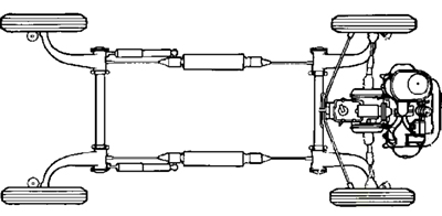
Hello fellow Autopians and welcome to another edition of Ask An Engineer. Today we’re going to discuss the front suspension setup found on the Tesla Model S, BMW 3 Series, Dodge Charger, and an increasing number of sports cars. It’s called the “double pivot” or “double ball-joint” suspension, and its design results in the front wheels rotating about a virtual steering axis when you turn the steering wheel (instead of one defined by two physical points like you might expect). And the axis itself actually moves. Let’s look at how it works, and at the significant advantages it offers over a traditional setup.
This article is inspired by a question sent to me by a reader named Kevin. He asked about a comment I made a while ago where I stated that having a steering rack located in front of the front axle had some advantages (like steering feel). He asked why this was and whether a double pivot front suspension also benefits from the rack being in the front. The answer is a very definite “Yes.”
Before we get into that and so much more, you may be wondering what this double pivot suspension Kevin is asking about is, and why it matters when it comes to steering gear position. Let’s start by looking at some front suspension design history.
[Editor’s Note: A quick note on the headline: Huibert was indeed a Tesla engineer, but he was also a Ford engineer (he worked on the Ford GT), and an engineer for a number of other companies. We chose that headline because it’ll interest more of you, but you should know that Huibert hasn’t worked there for quite some time. -DT].
Front Suspension History
For the first 30 to 40 years of automotive history, front suspensions consisted of a steel beam mounted on one or two leaf springs. They were simple, and while effective, they weren’t particularly comfortable and their directional stability left much to be desired. Starting in the late 30’s and 40’s, a new kind of front suspension came onto the scene, ditching the beam and mounting each wheel independently to the vehicle using a pair of A-arms or wishbones in a configuration that became known as the double wishbone. There were other permutations of an independent front suspension; the VW Beetle had two parallel trailing arms and the Citroen 2CV had a forward facing single arm, but the majority of passenger cars were migrating to the double wishbone design.


Above we see a typical front suspension of the time with its stamped steel upper and lower arms attaching to a steel knuckle with a ball joint at the top and another one at the bottom. The steering axis, or kingpin axis, is formed by a line going through the centers of the upper and lower ball joints, and represents the axis which the knuckle/wheel pivots around when the car is steered.

A few years later saw the introduction of a new type of independent front suspension, the MacPherson strut, shown above. Invented in 1945 by Earl MacPherson, it didn’t see regular production use until the early 50’s and didn’t really become prevalent until much later. The success of front wheel drive in the 70’s saw an explosion of MacPherson struts since their more compact design was better for the small cars and transverse engine placement that became popular along with front wheel drive.
Like the double wishbone design, the kingpin/steering axis in the MacPherson strut goes through the center of the lower ball joint, but unlike the double wishbone, there is no upper ball joint to help define where the kingpin axis is. Instead, the upper pivot in a MacPherson is at the top of the spring where a bearing allows the entire knuckle and spring assembly to pivot when the car is steered. This upper pivot along with the lower ball joint is what defines the kingpin axis in a MacPherson strut.
How A Traditional Suspension Compromises Brake Size

Why A Traditional Suspension Has To Move The Ball Joint Towards The Brakes To Minimize ‘Scrub Radius’
Both the MacPherson Strut and the double wishbone designs share a common feature, which is a lower control arm with a single ball joint attaching it to the knuckle. Since this lower ball joint helps to define the kingpin axis, its location is critical. At this point it is important to understand that suspension engineers try to place the kingpin axis as far outboard as possible in order to minimize something called the scrub radius. This is the distance between the point where the kingpin axis intersects the ground and the center of the tire contact patch when the car is viewed from the front.

You can visualize scrub radius by watching this video; you can see that the tire isn’t just spinning about a vertical axis going through its center (like a coin would if you flicked it on a tabletop), it’s making a “sweeping” motion, the nature of which can be described by the scrub radius:
Above (and pasted again below) we see a cross section of a tire with the lower ball joint and the kingpin/steering axis going through it. In the case of the diagram, the intersection of the kingpin axis with the ground happens inboard of the tire contact patch. When this happens, the scrub radius is said to be positive. If the kingpin axis were to intersect the ground outboard of the tire contact patch then the scrub radius is said to be negative.
The reason suspension engineers try to minimize the scrub radius is that, when the brakes are applied, the braking force and the scrub radius cause a torque to be applied that tries to steer the wheel. You can visualize that in the image below; if the ground is pushing the tire backwards at the contact patch, which is a few millimeters outboard of where the kingpin axis intersects with the ground, that tire is going to want to rotate, which will pull on the steering tie rod, sending forces to the steering wheel.
Normally, when braking on dry pavement, we have equal braking forces on the left and right wheels, which together with the scrub radius create equal and opposite torques applied on the left and right wheels. They cancel each other out (they both push or pull the steering rack with similar forces). But when one wheel is on a slippery surface such as wet pavement or ice, the braking forces are not equal and therefore the left and right torques caused by the scrub radius are also not equal. If the suspension was designed with a large scrub radius, these torques could rip the wheel out of your hands or at least cause the wheel to turn suddenly. You can see why suspension engineers try to minimize the scrub radius as much as possible.

So, if we want to minimize the scrub radius, and if the lower ball joint defines where the kingpin axis is (which defines how big the scrub radius is), then it stands to reason that we want the lower ball joint to be placed as far outboard as possible. Unfortunately, the lower ball joint is not the only thing that has to fit inside the wheel. We also need brakes, and they get in the way. Let’s look at how the brakes fit inside the wheel.
This Creates Brake Packaging Struggles

Here we see a typical brake package inside a wheel. The caliper is packaged as close as possible to the inside face of the wheel and as close to the rim section as possible. This gives the largest diameter brake rotor. Notice also that the lower ball joint is sitting very close to the rotor and that it really can’t go any farther outboard. As it is, we have to be very careful here because the heat from the brake rotor can melt the rubber boot that protects the ball joint, so we have to stay at least far enough away from the rotor to allow a heat shield to fit in between the two parts. You can see how we are really limited on how far we can push the lower ball joint outboard.
You can also see how the dropwell of the rim limits where we can put the brake caliper and hence how large a brake rotor we can fit. In modern cars, with 18-inch, 19-inch, and even larger wheels becoming more common, this isn’t really much of a problem since the rim is far enough away from the calipers that we can fit almost any size brake rotor we want, but back in the 60’s and 70’s, 13 and 14-inch wheels were the norm while 15-inches was considered a large wheel at that time. With diameters so small, you can see how the rim section would have forced a much smaller brake rotor in order to fit the calipers inside these wheels. In fact, nine and 10-inch diameter brake rotors were commonplace while today 12-inch and even 14-inch rotors are often used. For a 15-inch wheel, the largest brake rotor anyone was able to fit back then was about 11 inches in diameter — large by the standards of the day but not sufficient for a fast car that needed to be able to stop as fast as it could accelerate.
How A Traditional Suspension Compromises Steering Feel

Why A Traditional Suspension Usually Has The Steering Rack Behind The Axle, And Why That’s Bad
It’s not just braking concerns that the Double Ball-Joint suspension aims to improve, it’s also steering feel.
One thing that automakers tend to do is build understeer into their suspensions as a way to maximize vehicle safety should you overcook a turn (the front of a car is designed to crash into things; it’s generally considered better to understeer into something than to go sideways and possibly roll over). David Tracy (who edited this article) discussed how Ford does this with the Ford Bronco Raptor’s “roll steer,” but I’ll talk about how automakers do it with front suspension bushing compliance. Put simply, one way to do it is to make it such that, when you’re turning, the lateral loads on the tire deform bushings in a way that promotes the tire steering away from the turn.
What you don’t want to deform are the steering rack bushings. Ideally, you want the rack to be hard mounted to the vehicle structure, because that means the loads imparted during turns will end up at the steering wheel instead of being absorbed by squishy rubber, and you’ll enjoy the precise steering feel that everyone likes on a nice-handling sports car. Instead, you want the bushings in the lower control arm to deflect, like the ones in the diagram below do during a left turn — notice how the control arm bushings deflecting while the tie rod stays firm causes the tire to rotate away from the turn, inducing understeer.

This stiff steering/nice steering feedback really only works if the steering rack is ahead of the axle. If you move the rack behind the axle centerline, you have to build bushing compliance into the rack itself in order to induce understeer during cornering, and you also have to make the suspension bushings stiff, which can have adverse ride quality effects. Check out what you have to do with a rear-mounted rack to build in understeer:

Obviously, a bad ride and sloppy steering isn’t optimal, so you’d ideally want the rack up front; the problem is that a traditional suspension design generally requires the rack behind the wheel. Why? It has to do with a concept called Ackerman.
Ackerman Puts The Rack Behind The Axle On A Traditional Suspension Setup

When you turn the steering wheel of your car to navigate a turn, the inner and outer tires are tracing circles of different radii. So to smoothly navigate the turn, the inner wheel should turn a bit more than the outer wheel. You might have noticed that to be the case just looking at the front end of a car whose wheels are cranked hard to one side:

The way you achieve Ackermann with a traditional suspension setup is to make sure that the line from the lower ball joint through where the steering tie rod mounts to the knuckle goes directly to the center of the rear axle. Like so:

Here’s a little animation of how this setup yields proper Ackermann:

(Note: It’s a little hard to imagine how that steering set up causes a difference in steering angle depending upon whether the wheel is on the inside or outside of the turn, especially given that the rack is moving the steering arm on each side the same amount. What it comes down to is that the perpendicular distance between the tie rod and the kingpin axis needs to get shorter on the inside wheel and longer in the outside wheel so that the inside wheel turns more for each inch of rack travel and the outside wheel turns less. Again, it’s a little hard to visualize, but that’s not really that important).
You could also build in the appropriate Ackermann in a similar way with a steering rack mounted ahead of the front axle, but the point where the tie rods intersect the knuckle would still need to be on the line between the ball joint and the center of the rear axle, meaning the tie rod would be quite far outboard, likely interfering with brakes, or at the very least compromising brake size.

So, with a traditional MacPherson strut or double wishbone design, in order to minimize scrub radius, provide the necessary understeer, and have good Ackermann, you end up with a lower ball joint located far outboard and a softly mounted steering rack located behind the axle centerline, possibly resulting in less-than optimal steering feel. The Double Ball Joint suspension doesn’t have these problems.
The Double Ball Joint To The Rescue
In the early 70’s, BMW decided it had enough of these tradeoffs, so they went about inventing a new kind of front suspension. The solution was to split the lower control arm into two pieces and connect each one to the knuckle with its own ball joint: It’s called the double ball joint front suspension, or double pivot as Kevin called it in his question. BMW placed the two ball joints much farther inboard than the conventional single ball joint design, and this allowed BMW to move the brake rotor inboard as well. Getting away from the dropwell in the rim allowed BMW to move the caliper radially away from the wheel center and fit a much bigger brake rotor. You can see what the effect was here:

Although the image doesn’t show it as well, BMW was able to use this design to get a 12-inch brake rotor into the same 15-inch wheel that everyone else could only get an 11-inch rotor into. This was a really big deal that gave the company a distinct advantage over its competition, especially on the Autobahn where braking power was and still is extremely important.
The Virtual Ball Joint Allows Room For Big Brakes
Looking at the image above, some of you may have noticed that the kingpin axis does NOT go through the lower ball joint. How can that be? We already stated that the kingpin axis goes through the center of the lower ball joint, but when there are two ball joints instead of one, which one does the kingpin axis go through? The answer is neither. The two ball joints create what is called a “virtual” ball joint and thereby a virtual kingpin axis. Here’s how it works:

Looking at the suspension from below, draw lines through the inner bushings of the two lower links and through the corresponding two outer ball joints as shown in the picture above. Extend these lines until they intersect (the photo angle makes the virtual lower ball joint look a bit farther outboard than in reality). The point at which they intersect is the “virtual” ball joint, which is then used to define where the kingpin axis is in the same way as the single lower ball joint did in the traditional double wishbone design
In reality, it’s not quite that simple, because if you look carefully, the lower control arms mount to the chassis on a different Z-plane, so the two lines do not actually intersect, even though it might look like they do from directly below. To really find the kingpin axis (which we need to know to determine things like scrub radius, caster angle and a number of other suspension parameters related to the location of the kingpin axis), we just make a couple of planes. Remember from High School Geometry class how you can define a plane using three points? If you take the center of the upper ball joint (or the center of the upper spring mount in the case of a MacPherson strut) along with the center of one of the inner bushings and the center of the corresponding lower ball joint, you have three points that define a plane. Similarly, if you use the center of the same upper ball joint (or upper spring mount) along with the center of the other inner bushing and its corresponding outer ball joint, you get three more points that define another plane. Where these two planes intersect is the kingpin axis. With this method you can create the equation of the line that represents the kingpin axis and calculate the scrub radius, caster angle and anything else you need to know related to the location of this axis.


Notice how much further inboard our two ball joints are relative to the “virtual” ball joint. This is space that can be used to pull the brake rotor inboard and away from the dropwell in the rim. That allows us to move the caliper radially away from the wheel center and fit a much bigger brake rotor.
The Double Pivot Suspension Needs To Be Up Front To Achieve Its Ackermann Goals, And That’s Good For Steering Feel
Pretty cool, eh? Yes it is, until you start to steer the car and then things get really weird. It’s complicated and probably best to explain by showing you.
Unlike in a traditional front suspension, the steering gear in a Double Pivot setup actually prefers to be in front of the axle centerline; in fact, it’s pretty much required to be up front. Now I know there are some manufacturers that have used a double pivot suspension with the steering gear located behind the axle centerline (Acura did it with the RLX and Mazda did it with the Mazda 6 many years ago) but these cars suffer from the same distinct disadvantage that comes with such a steering gear placement, namely a large turning circle. The RLX turning diameter is 40.5-feet which is almost two feet larger than its worst competitor, the Volvo S90 and almost six feet larger than the Lexus GS. I contend this is because of the location of the steering gear that Honda chose for this vehicle. Any insiders out there wishing to enlighten me? I am all ears.
Why? Because whereas on a traditional suspension you achieve Ackermann by placing the tie rod-to-knuckle interface on a line between the ball joint and the center of the rear axle, on a Double Ball Joint suspension, the steering/kingpin axis actually moves, and it’s the movement of this axis that causes the inside wheel to turn harder than the outside one.


The easiest way to understand that is to realize that the wheel and tire rotates about a virtual axis that changes positions, moving forward on the inside wheel and backwards on the outside wheel. For simplicity, you can just imagine that the inside wheel spins about the ball joint closest to its tie rod (the front ball joint) and the outside wheel rotates about the ball joint farthest from the tie rod (the rear ball joint). And we all know that a given linear displacement at a large radius arm is going to swing a smaller arc (and thus rotate less) than that same displacement pushing on a short radius arm. Here’s a video of David at a junkyard walking you through the Double Pivot suspension’s Ackermann motion:
Still think the double ball joint design is cool? Well, so do I and it’s the reason I’ve used it in several cars that I’ve worked on in my career. There is only one downside to this design, and that is cost. Ball joints are not cheap and having two instead of one per side definitely adds to the cost of the suspension. For cars at the low end of the price spectrum, this additional cost may be too much which is why you see this design primarily in higher end cars and SUV’s.
One final word: It doesn’t matter if you have an internal combustion engine or an electric motor, the advantages of the double ball joint design are the same. In fact, it’s the size of internal combustion engines that often get in the way of putting the steering gear where we want it. With EV motors being so much smaller, I think we will see more use of the double ball joint design simply because of the advantages we’ve talked about here.


A big thanks to Kevin for sending me this question. If any of you have any other automotive engineering type questions, please send them to AskAnEngineer@theautopian.com and I will do my best to answer them.


Suggestion for this kind of article:
CAD animations are the best way to illustrate mechanicals.
Blurry pics of rusty suspension parts are not useful to those of us that aren’t engineers or experienced mechanics.
Lego models are also great for demonstration purposes.
I’m still looking for a good way to model these kinds of things. CAD packages that show motion are quite expensive and beyond the means of your humble author. What I need is something like an erector set that will allow me to make mechanisms and film them.
I have done this in the past using Catia. Here’s the link if you want to check it out:
https://m.youtube.com/watch?v=D1MsE2zlUAA
The licences for that are crazy expensive, but I may have an older cracked version laying around in a hard drive somewhere, from my studying years.
Maybe give GIMP a try? It’s free and I know you can animate and film stuff.
It’s actually reasonably simple if you have any package that can solve non-linear simultaneously equations (mathcad for example). Each link can be represented as a length constraint.
Ok that’s interesting.I was wondering why you kept saying a front steering rack is better. The answer was pretty simple in the end!
Very neat.
I think I understand most of that. 🙂 The upside is bigger brakes & you can put the steering rack behind if that fits the packaging better, the downside is more cost & complexity.
Wouldn’t electric cars with regenerative braking and smaller motors eliminate most of the advantages of the double ball joint setup?
I was thinking the same thing about EV’s needing smaller brakes. Here’s my thoughts. 1) regenerative braking does lead to less actual brake use. 2) EV’s a heavy AF so when there is hard braking, the rotors need to be big to stop all that mass. 3) Teslas are expensive and people expect expensive cars to have big brakes with painted calipers.
In a way they do but regenerative brakes can only do so much. In an emergency stop, especially one where ABS kicks in, regenerative braking isn’t very helpful and may even get turned off by the control system. In that event, you’re relying purely on the mechanical brakes and they need to be up to the task.
Stuff like this makes me want a Trike riding on leaf springs on a straight axle in the rear and symmetrical motorcycle style front suspension. Minimal suspension complexity, nothing really to align, with proper front steering design you can have a front wheel that spins 360 degrees.
KISS
That explains the upper and lower front control arms.
Great Explanation. Now I see why my old go-cart had the steering gear in front, the spindle arms for the tie rods were on an angle, and why when fully locked to one side, one wheel pivoted more that the other. I think Honda (1990’s Civics)had a better design with the upper control arm ball joint located over top of the center of the tire(where mud could splash on it), with super-tall spindle extensions. It was all cast Aluminum so UN-sprung weight was not a problem. The Chrysler Cloud Cars used it also. It was very easy to repair and cheap(er) to make than this.
The take-away is that front-end alignments will require PHD level Scien-ticians costing $2K, and ball joint repair will be the new name for “Short-Term Lease”.
I remember when Mercedes came out with their new 5-link independent rear suspension. One curious Engineer at their press conference stated that the only way he could see that it could work, was by severely compressing the rubber bushings, resulting in a short life-cycle, causing expensive near-term repairs. The Executive responded; “Yes. Next question.”.
This was my general takeaway from this complex explanation of why increased complexity improves ride but costs more to design, make, and maintain.
I really appreciated your explanation on this topic, especially that super charming video. As a Systems Engineer for a medical device company, I spend a lot of time explaining highly technical concepts to diverse groups of technical and non-technical people. I can only aspire to making my explanations as clear, concise, and approachable as yours. Thank you for the inspiration.
Of course, there’s another solution to the issue of the steering arms getting in the way of the brake rotors: Inboard brakes 😉
I’m man enough to admit I got lost in this.. I’m grateful for engineers that do this stuff for a living, I can fix most of my car but I know I can’t engineer it!
Loved this on my 02 Allroad for the great ride, roll, and steering characteristics. That car had it on both the upper and lower control arms. Didn’t love the accelerated bushing wear, but hey you gotta pay to play.
Thanks for this and taking the time to spell it out.
I thought I was getting a handle on it, but that diagram with the point of intersection made it click on my simple brain, which more or less understands four link live rear axles and virtual ladder bars and all of a sudden it was the same thing, just different. (-:
The concepts are exactly the same as you noted. The double ball joint turns the front suspension into a 4-bar link, just like the 4 links in your rear axle do. They just serve a different purpose but the concept is the same. Good observation!
Before I even read the article, I’d like to point out the name of the image for this article is “doubleballs_top.jpg”. Nice.
So looks like to reduce scrub radius you can have higher offset wheel with skinnier tire to pull the tire inward? Is that a reason why most cars look like they designed fenders that are too big for the wheels?
You could do that but the wheel would soon start to look pretty weird. If the main part of the wheel sticks out beyond the rim section or the tire then you have a big risk of curb rash. It also wouldn’t help your brake package very much since the drop well of the rim would still limit the diameter of the rotor. The idea is to get the brakes inboard of the wheel drop well so that you can get a bigger diameter rotor in there.
So the Honda Type R has a double ball joint but one ball joint on the bottom and one on the top. I remember reading about it’s special setup to reduce torque steer on a front front layout. Does this have the same concept?
I think the type R is a different thing. It has a single ball joint on the bottom, on the top it has a ball joint offset outboard from the axis of the Strut. The position of the ball joints sort of mimics a double wishbone suspension and gets rid of most of the scrub radius. The knuckle pivots around those two ball joints, like a double wishbone, not the lower ball joint and the top of the strut. I think their main goal with that was to get rid of the torque steer that you normally see on FWD.
The double ball joint concept here is creating a point in space that the knuckle pivots around. And that point is space moves as you steer.
Well explained. Thank you.
yes, honda used to have this setup on all their cars in the late 80’s and 90’s. Because of that weird knuckle the wheels and tired could not o to wide. I think a 225 width tire was the max you could have on them. Also this setup had a very long upper control arm, and when correcting camber after lowering the vehicle more than 1.5″ the control arm would hit the inner fender, rendering the springs useless 🙂 Live and learn, i guess.
All double wishbone suspensions have one ball joint at the bottom and one at the top. That is not the “double ball joint” I’m talking about here. In the design I’m talking about there are actually 3 ball joints: one at the top and two at the bottom of the knuckle.
Dragging the high school geometry into it was helpful. Things finally started to click a little. To take those concepts a little further, do I have this right: If you were to graph every possible position in space of a lower ball joint in a single lower ball system you would have a circular arc (two dimensional motion) centered around the axis running between the fore and aft control arm mount points on the frame. If you graph every possible position of the lower joints in a double system you would have two spherical sections (three dimensional motion) centered on the frame mount points of each arm. (Ignoring the displacement allowed for by complaint bushings.) Correct?
Yes, that is correct. The trick is to know where on each sphere you are at any given time since the distance between the two points must always be the same. One you know the position of those points at any given suspension position and steering angle then you can use the two plane method to find the kingpin axis and all the corresponding parameters like scrub radius, caster angle, caster trail, etc.
For what it’s worth, the Chrysler LX cars devour those lower control arms/tension struts. If you have a clunk in the front end of an LX car, chances are those are the culprit.
This type of content is why I spend my day here. More please!
I’m curious how Camber and Castor are affected? And also the braking. Thanks
They aren’t. Camber and caster are still the same but caster is now the angle of the virtual kingpin axis. And since the kingpin axis moves around during steering, so does the caster angle. It’s not a problem, just something to deal with during the suspension design
Neat! the Ackerman part explains why older trucks always seemed to have the tie-rods in front of the axle instead of behind where they’d be more protected.
Those older trucks used an older type of steering system that would tolerate much larger scrub radii. The kingpin on those vehicles is much further inboard and will allow for a front mounted steering system while still getting good Ackerman. I’m working on a post that will explain this more clearly.
Thank you for this article and the excellent video, I hadn’t heard of the double ball joint design. In university FSAE (circa 2013) we struggled with getting Ackerman into a front steer design (without making the scrub radius even worse than it was) dictacted by the location of the steering wheel and steering shaft geometry. Apparently double ball joints were the answer! If only we knew, haha.
Any good books or online classes on this?
I might have a project in the future trying to package part time AWD into a small British sports-car. (Think Superfast Matt’s Honda 600, but British and with a paddle on the steering wheel to send a variable amount of torque to the front wheels when exiting a corner.) Hoping to use period correct wheels which don’t tend to have the offset that things do today, so double ball joints would help on the packaging and torque steer.
Book here, https://www.chassissim.com/product/the-dynamics-of-the-race-car/
And they have online sim software, though not exactly sure of the capabilities in terms of figuring out suspension design. https://www.chassissim.com/online-sim/
Not that I’m aware of, I’m afraid
Race car vehicle dynamics is supposed to be quite thorough, don’t know if it addresses this geometry though
Very interesting article! Keep interesting stuff like this coming!
Thanks for the explanation! This setup confused the hell out of me the first time I saw it (on a Mitsubishi Eclipse, I think). But now that I understand why it’s done, it makes perfect sense. It does bring up another question, though: are there any advantages or disadvantages to this setup on a front-wheel-drive car vs rear?
No, it can be used for either front or rear wheel drive
Great article Huibert. I would just like to add that front wheel drive requires more consideration of the hub offset, which double ball joint can also help to reduce (with a negative ground offset).
Thank you. I’m smarter now.
My Audi Allroad had the double balljoints at the top rather the lower control arm, but still had the rack behind the front wheels?
Hopefully you never had to replace those control arms. I had to do them on a B5 Passat and fuck me. 4 control arms per side and after 60-70K miles they just didn’t wanna come out.
Check your Allroad again. I’m pretty sure you’ll find double ball joints at the top as well as on the bottom. VW/Audi has had that design for quite a while now but i don’t really see what benefit they’re getting out of it. It sends an unnecessary cost to me
I’m pretty sure it has to do with the insane way VAG cars are packaged with their FWD/AWD systems with longitudinal engines. They eliminate a separate front differential by making it part of the transmission package. That means the front axles come from the transmission behind the engine. To make that work they push the engine itself forward making the car nose heavy and with no space between the engine and radiator core. (Hence the infamous VW/Audi service position.) That also eliminates the typical locations for the steering rack below the engine. Instead it’s placed above the transmission with the rack attached at the top.