
We recently celebrated our first birthday here at The Autopian, the founders alternately holding yet another fun event TO WHICH I WASN’T INVITED and by blowing the remains of the housekeeping money for the year on a diminutive two stroke roadster. It’s the only thing around here that smokes more than me. But did you know how the early editions of this website came about? Torch created them during feverish all night coding sessions, hunched over his Osborne 1 powered by nothing but a desperate mania to be heard and copious amounts of fluorescent energy drinks. He’d wire the pages out every morning to paying members via a teleprinter. Eventually David and Beau took pity on him and our IT infrastructure was given a hefty upgrade to a Sinclair QL complete with Microdrive, resulting in the high-quality website pleasuring your eyeballs are right now.
Coming to The Autopian tomorrow: We explain how @JasonTorchinsky and @BeauBoeckmann ended up buying a spectacular, silly car at auction. pic.twitter.com/lxQEyWWAXC
— The Autopian (@the_autopian) April 3, 2023
Read enough below the line commentary on the platform of your choice (although, really you should be getting all your automotive content here and nowhere else or we’ll send the goons round) and accompanying every new model reveal there’ll be some coffin dodger griping that new car designs lack soul and emotion, and nothing good has been released since about 1970, to pull some arbitrary date out of my ass. They’ll inevitably place the blame for this on computers, as if cars used to be designed and forged on an anvil of enthusiasm by REAL MEN WITH PETROL NOT MICROCHIPS IN THEIR VEINS or some other such utter horseshit. Yep, those halcyon days when designers could smoke in the studio, had to wear a suit and did twelve-hour days (with no overtime) breathing in noxious marker fumes, chalk dust and God knows what kind of industrial solvents and women were nowhere to be seen.

Aren’t CAD and CAM The Same Thing?
Well I’ve got bad news for you, pops; computers have been a part of how cars are made for a very long time. The history of computers in car design and manufacturing goes back pretty much all the way to the first transistorized second-generation mainframes in the late fifties. But the mainstream never really caught onto it until CAD/CAM became a buzzword in the electronic eighties when OEMs plastered it all over their advertising copy to show how bleeding edge they were.
They might seem interchangeable, but actually Computer Aided Design and Computer Aided Manufacturing are really two distinct but related things. When it came to car design, a unique type of modeling software was required to enable studios to use “the tubes” to transform their marker and paper sketches into computerized sheet metal. We’ll get to why car designers are so special they need their own software in a bit, but first let’s take a little history lesson which I promise won’t be full of math (mainly because I don’t understand the math either, and it’s boring).
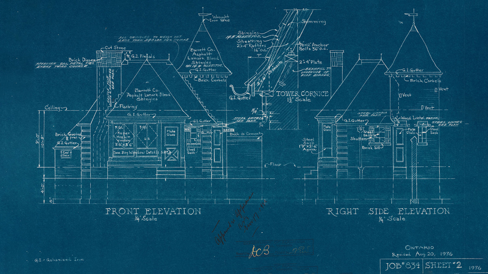
Blueprinting was the original method of reproducing technical drawings. For the first time it became possible to create a technical specification drawing and distribute it maintaining accuracy and scale. The blue background made alteration impossible, so draftsmen could be sure that people using their drawings were following the given specifications exactly, useful in avoiding a Spinal Tap Stonehenge type situation. This empowered much of the industrial revolution of the late 19th century, but as a duplication method it was well obsolete by the time photocopying was introduced in 1959. (Incidentally, this is where the term ‘blueprinting’ for engines came from. Back when mass production tolerances resulted in spectacular variations in production quality, an engine hand built to the given specs would result in more power).
The ancestor of all computer aided interaction in design can be traced back to a program called Sketchpad, invented by Ivan Sutherland [Editor’s Note: Later, this same guy also scanned the first real object into a 3d wireframe. That object was a Volkswagen Beetle! – JT] for his PhD thesis at MIT in 1963. It used a light pen to interact directly on an oscilloscope screen to create rudimentary technical drawings. It might look primitive but it demonstrated several key advantages over traditional drafting methods; repeatable dimensional accuracy, the ability to store, retrieve and reproduce identical drawings, and instances, which is a duplicate that changes when the original drawing is changed. But the main advances Sketchpad introduced were twofold: it translated lines and circles on a screen into mathematical geometry that could be stored, understood and manipulated by a computer. And it was the first time that a human could interact with a computer using a GUI (Graphical User Interface).

General Motors
Computers had been introduced into milling machines as early as 1953 – using time and XYZ inputs to move a cutting head – Computer Numerical Control (CNC). General Motors did a lot of research into how computers could help the whole design process – they found that every stage from initial sketches through to body design and final tooling used different drawings and each department had its own drafting department. Working with IBM, they developed the DAC-1 (Design Augmented by Computers) running on an IBM 7090. This allowed the storage and retrieval of a unified set of drawings for everyone involved could access, and designers could even sketch with a light pen. But the data input and manipulation still had to be programmed in with a punch card.
In 1971 Patrick Hanratty (sometimes called the father of CAD/CAM) created Automated Drafting and Machinery (ADAM) for GM. For the first time it was possible to provide the data to create tool paths directly from technical drawings created digitally on a screen. CAD and CAM had finally gotten together to become one seamless process.

IBM DAC-1
But this was still only technical drawings created in 2D – the computing horsepower required for 3D didn’t really exist yet – although the original Sketchpad had been later been reprogrammed with the ability to display and rotate 3D wireframe images. For engineers this didn’t really matter too much – they’d been used to working from paper drawings anyway and the parts they designed were very geometrically shaped variations of simple primitives like cubes, cylinders and rectangles combined together. They didn’t need to be aesthetically pleasing, because the customer wouldn’t see them (these are known as ‘B’ surfaces). But for designers creating sculptural bodywork and surfaces a customer could see and touch (known as ‘A’ surfaces) a way was needed to harness this emerging technology to turn their ideas into data a computer could understand.
It Was a Math Problem
The problem was it was hard to create the more organic shape of a car’s bodywork mathematically. There was no way for a designer to create freeform curves directly on a computer. Think about it like a Lego Technic set. For the underlying mechanicals of a model vehicle it’s brilliant – but when it comes to recreating the bodywork its limitations are clearly exposed, because it wasn’t designed for those complicated compound shapes and surfaces.

Designers would work closely with clay modelers to turn their 2D marker and pastel sketches into physical models. Once a design was frozen and signed off by management, a mahogany (or sometimes plaster) buck would be made, to allow the tool makers to create the dies that would stamp out the panels. This was the master – the bible for all the external dimensions and shape of the car. Body engineers would use this as the basis to figure out how the car would be built. The problem was with so many stages, different materials, nearly 20,000 technical drawings and fallible humans involved there was a lot of scope for fucking it up. If you’ve ever wondered why the panel fit of older cars is often appalling, now you know. If a car’s shape could be turned into 3D data points and fed directly into a computer, then a more accurate, quicker and cheaper reference for drawings and tools would be the result.

Clay models were (and still are) sculpted on a perfectly flat metal floor, known as a plate. A device called a styling bridge, a large upside down U that straddles the model, could be rolled back and forth to take measurements using a series of dowels touching the clay at set intervals and then transferred over the Y axis to make sure both sides were symmetrical. This unwieldy contraption could also take dimensions in any of the three axes of the surfaces of the model in relation to the origin point. Scanners did eventually become available that could capture body shape from a full size model numerically, but this then had to be converted into CNC inputs which were imperfect because the conversion algorithms were error prone. By 1967 this analog process was digitized and further hernias avoided, by an Italian company who invented the Corporate Measuring Machine which used a metal probe mounted on a gantry powered by stepper motors to move it in three dimensions across the model. But designers were not interested in milling machines – they were more interested in getting a computer to realize their designs rather than draftsmen, a process that could take months.
What Boats Have To Do With It
The first OEM to come up with a way of creating a body shape directly in data was Renault, thanks to the work of engineer Pierre Bezier. He was influenced by shipbuilding methods from hundreds of years ago, when draftsmen used thin strips of wood as templates for hull designs. These strips could be bent to the desired shape and then fixed in place using heavy metal pucks to hold the curvature. Bezier’s breakthrough was realizing points near a curve could be used to define its shape, as opposed to points on the curve itself (similar to using the pen tool in Illustrator or Photoshop). Therefore, a computer using a preset algorithm could figure out the shape of a given curve if it knew the coordinates of these control points. This meant that you could use a series of these curves to define a surface. Coincidentally parallel research was taking place at the same time at archrivals Citroën by Paul de Castlejau but they kept it secret until the eighties, which is why Bezier gets the curves named after him.
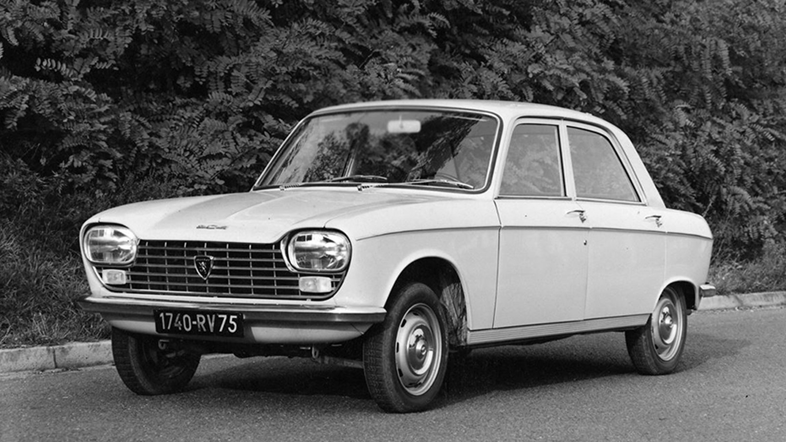

The Renault system was called UNISURF and they were initially reluctant to embrace this ‘freeform curves drawn on a computer’ witchcraft, but Peugeot said oui s’il te plait after signing a 1966 technology sharing agreement with them. The Peugeot 204 of 1968 is one of the first cars to have its body designed completely using the CAD/CAM pipeline. The first Renault designed using CAD was the 14 of 1977.
How Boeing Helped Kickstart a Revolution in Car Design

As is so often the case with emergent technologies, everybody and their dog was coming up with their own proprietary CAD/CAM systems. VW developed a program called VW SURF, first used on the MKII Golf of 1983. In 1979, Boeing was researching a CAD/CAM system of its own called TIGER. Its developers realized they could use Bezier curves with another mathematical concept known as a B Spline to create something called a NURBS – Non Uniform Rational B Spline. A fully mathematical representation of a 3D surface using control points. Boeing proposed including NURBS in the new IGES file format for exchanging CAD data, and due to their size and influence it was accepted. Now there was an accepted, interoperable cross industry standard, the CAD race was truly on.
Alias/1, another NURBS based modelling program was introduced in 1985. By the mid to late eighties all the domestic OEMs were using NURBS modelling software in one form or another. Chrysler was using Alias and a program called CDRS (Conceptual Design and Rendering System) developed by creator of Sketchpad, Ivan Sutherland. Ford also used CDRS and GM being GM had developed not one but two in house programs – CGS (Corporate Graphics System) and Cadence. All of these systems needed studio heating levels of computing firepower. Alias only ran on top of the line Silicon Graphics International workstations. Even by 1998 one of these babies would still require flexing the company plastic to the tune of $38,995 (nearly £72k today). Fortunately for the OEMs, Moore’s Law was delivering on PC clones – as Windows machines got more powerful they became capable of displaying 3D graphics with the help of plug-in cards, although 2D software like AutoCAD had been happily running on IBM PCs for years by now.

Alias was eventually ported over to Windows (a move that partly led to the insolvency of SGI) and folded into the burgeoning family of Autodesk CAD software, where it remains today as one of the two main NURBS modelling programs specifically aimed at automotive design studios. The other is ICEM Surf, which came about through the purchase of VW SURF by Dassault Systemes, a subsidiary of the company that will sell you a Rafale multi role combat jet. It’s part of their integrated suite of engineering software, including CATIA which is used by engineers to build the digital version of a car before a single part is made. If you’ve seen those engineering screengrabs online of upcoming models with all the parts in lurid colors, that’s almost certainly CATIA.


Why Automotive Designers Are Special
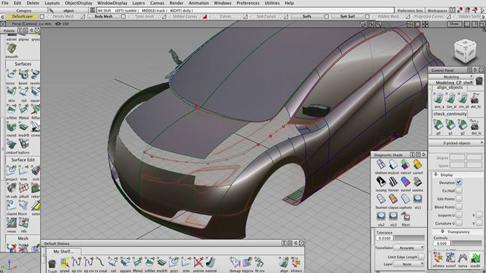
So why do designers, and by extension design studios, need their own expensive flavor of 3D modelling software? Blender is open source, widely supported and completely free. Blender is what is known as a Sub-D (subdivision) modeling program. Like Maya or 3DS Max, it uses polygons to create 3D solids. This is great for digitally representing things on a screen like game graphics, special effects or animation. In terms of processor power, it’s a lot less CPU intensive than NURBS. That’s because it doesn’t have the complicated math underneath it to provide the dimension accuracy down to the thousandths of a millimeter required for production tolerances. NURBS modeling is like creating a complete surface out of several patches of metal, just like the real thing. It won’t let you do things that aren’t physically possible.
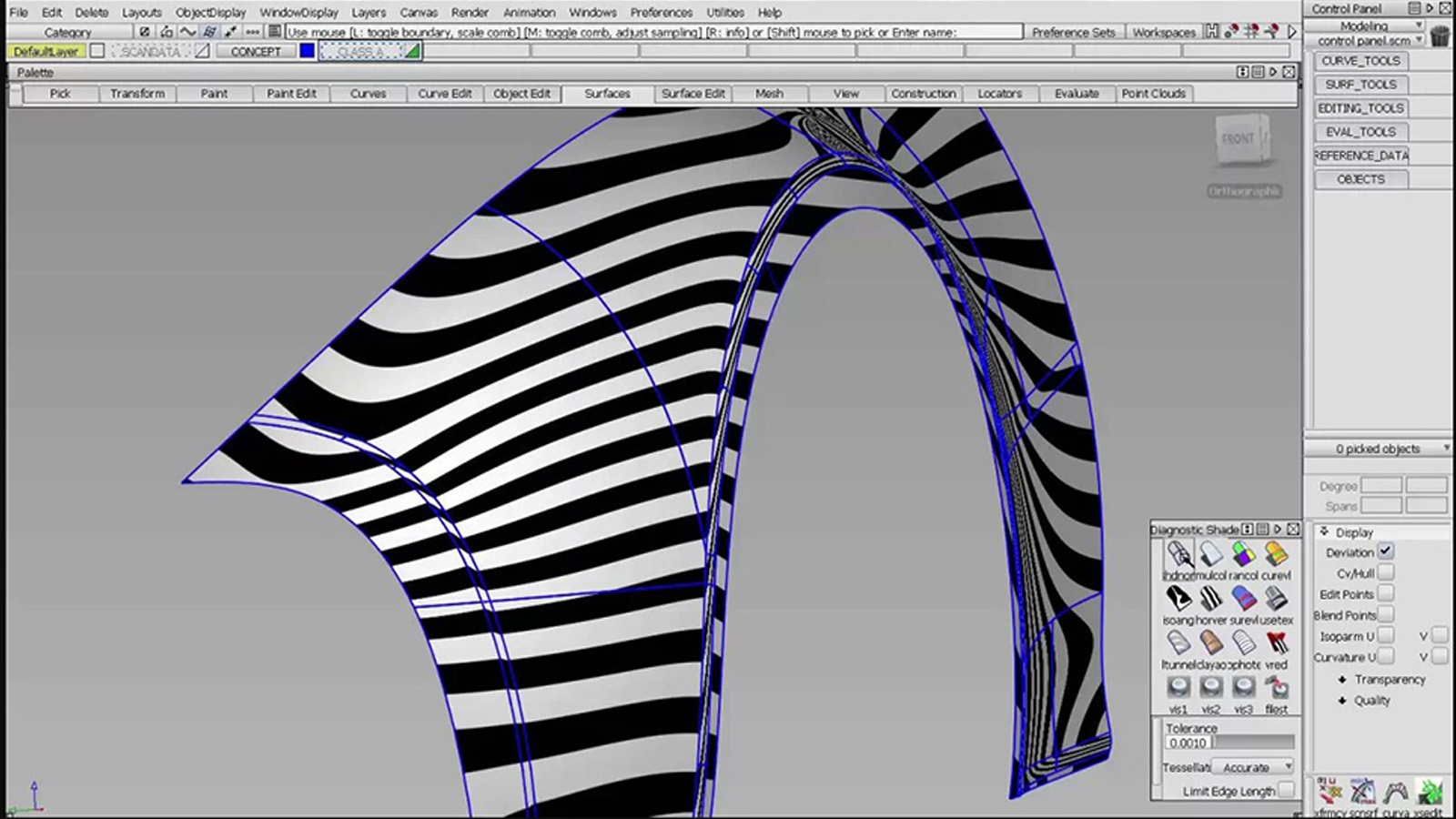
It gives you complete control over how the surfaces of your model are created, using control points to delicately sculpt each patch to ensure the correct continuity and tolerances with the patches around it. Both Alias and ICEM Surf comprehensive range of evaluation tools specific to the automotive industry, including the ability to check highlights across a surface and a shader to turn your model into a digital clay. It does have lighting and rendering capability, but for those functions you would transfer the model to a dedicated program like VRED (Autodesk again) or Unreal Engine.
Designers are not meant to be expert NURBS modelers – that is a separate role for CAD modelers. But they should be able to manipulate and tweak data they may have received from the surfacing team or use existing models to create something new. I spent an entire summer break during my undergrad course learning Alias, dutifully following all the tutorials to understand how to build a model of a car starting with nothing but a sketch and a few curves. That meant I was able to get my electric Hot Rod model looking exactly how I wanted (within the limits of my modeling ability).
 I was able to use this data not only to it milled at the university saving me thousands of pounds, but I was also able to use it to create renders as well, exactly the same processes that I would later use in a real design studio, albeit it at a much bigger and more expensive scale.

-
How Ford Could Have Made the Chrysler’s ‘Cab Forward’ Cars Before Chrysler Did
-
Meet The Lamborghini Concept Car That Inspired A Bunch Of Chrysler Sedans In The 1990s
-
The First ‘Realistic’ Computer Animation Was A Drive Down A Highway In 1961. Here’s A Look
-
Lexus’ NY Auto Show Display Uses AI To Create Photos And My God Are They Hilariously Bad


I’m a CATIA monkey most of the time and I dread using anything with a surface created by the styling studio. There are frequently weird little curves that you can’t extrapolate or offset, because maths. And sometimes they have holes in them, or tiny overlaps.
A few times I’ve had to re-model some styling data in to something we can actually work with. It’s normally within 0.01 of a millimetre (0.00039” for you lovely Americans who just need to convert to SI units already) of the holy data and as that’s well within the manufacturing tolerance of pretty much anything a-class no one has ever noticed. I can’t be the only one subverting the sacred styling surfaces.
“For engineers this didn’t really matter too much – they’d been used to working from paper drawings anyway and the parts they designed were very geometrically shaped variations of simple primitives like cubes, cylinders and rectangles combined together. They didn’t need to be aesthetically pleasing, because the customer wouldn’t see them (these are known as ‘B’ surfaces). “
You should see some of the wacky surfaces us engineers use in intake systems and cylinder heads. Fluid flow doesn’t like rectangles. You can even have some fun with exhaust pipes if you’ve got the budget for hydro forming.
I quite often see the blocky lazy CAD from “engineers” who are just throwing shapes so they can get to the next bit, and it makes me sad. It’s rare that the most elegant engineering solution is a rectangle with a lump cut out and some fillets, and yet that is so frequently what actually gets made. Sometimes you see a new component and you can visualise the model tree with the obvious extrusions and lazily imagined profiles.
The bits underneath can be beautiful, and with the right engineers they can be beautiful, lighter, cheaper and work better too.
I was simplifying for the sake of getting the fundamental point across, but yes I appreciate engineering parts can be incredibly complex, and have a beauty in their efficiency all of their own. But ultimately a mechanical part doesn’t have to have aesthetic appeal, although it might have some as a byproduct of its function.
Production surfaces go through many revisions, and certainly shouldn’t have holes. I know sometimes our studio engineers would ‘rough something in’ to start, because engineers outside of the design studio wouldn’t normally have access to anything regarding the appearance of the car.
I think the holes and overlaps are an issue with translating the a-class surface in to CATIA. They are only ever tiny fractions of a millimetre. You can do amazing things in CATIA, but sometimes it’ll just refuse to create geometry you know you is possible. I suspect it’s the programming equivalent of a French shrug.
Also sometimes a little dialogue box pops up with the message “click OK to terminate” with just one button underneath that’s marked “OK”. It’s never OK.
I left it too long to edit: CATIA V4 had this feature where you had to set the maximum size of your work volume, and the minimum size of any feature would scale with it. So when you set it for a 10 metre cube to fit a car in to, the features under 0.1 millimetre on the valve collets were too small to model, so we had to fudge them on to the 2D drawings instead. I wonder if V5 has some similar minimum limit of feature it’ll process. If so it’s tiny, but imported data might just find it.
I just tried to put a 0.001 millimetre fillet on a 100 metre long bar and it fell over. Anything longer than 100 metres “exceeds the model size”, any feature under 0.0011 millimetres “cannot be performed”. I didn’t start checking at 100 metres, I started at 1 AU and worked backwards because I’m ambitious/stupid.
It’s definitely possible to have what looks to be a straight line in imported data actually be a curve with a radius greater than 100 metres, in which case CATIA is going to start doing wacky shit. The instantaneous radius on a spline could easily flip out to something huge, and you’d never know until you try creating a feature based on it.
I wonder if this is a licence restriction on my version or just the upper limit of CATIA? It’s big enough to fit an Airbus A380, so I guess it doesn’t need to be any bigger.
I think this has clarified where the problem with styling data comes from, and it’s not the studio like we all assumed.
I’d never have gone digging in to this without your article Adrian. Thanks!
Finally got around to reading this.Very interesting!