


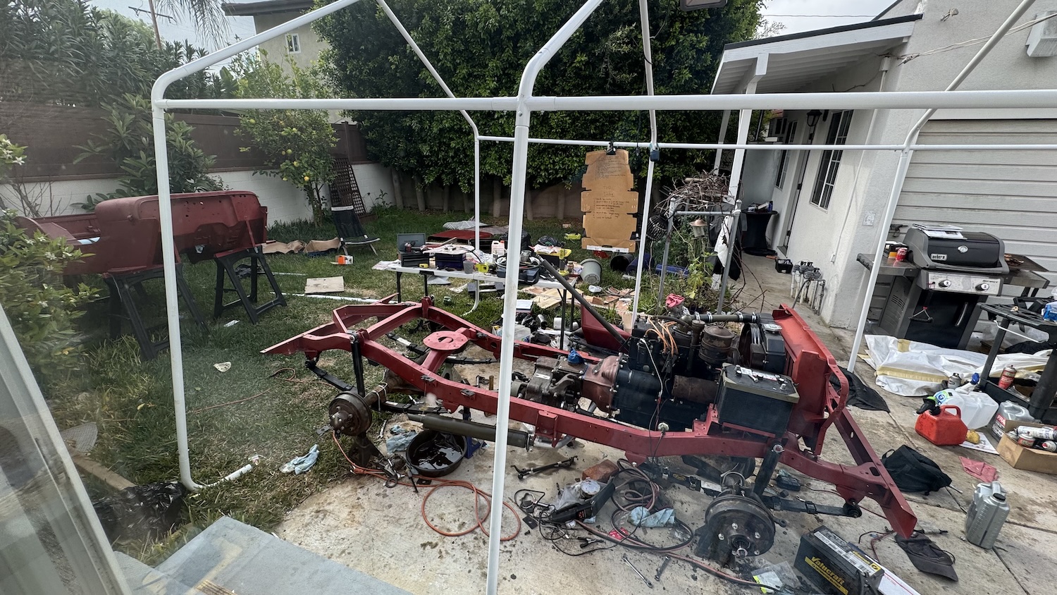
You’d think that a brand new World War II Jeep body would fit perfectly onto a brand new WWII Jeep frame, especially since both parts originated from the same Manila, Philippines factory. But that’s not how things went with my eBay WWII Jeep project. I was just just a couple of weeks out from a 900 mile journey in this brand new WWII Jeep I was building in my backyard primarily using parts from eBay Motors; I had no choice but to figure it out. Here’s what it took to get the iconic WWII Jeep body mounted.
Just three weeks before I was set to drive from LA to Moab, Utah, I found myself on a precipice. I had just enough time that getting this Jeep ready for the trip was theoretically possible, but I didn’t have enough time to have any confidence. That’s because I was not going to be able to do any validation testing; I knew I might be able to button up this Jeep enough to get it running and driving, but then I’d have to point it east towards Utah and pray.


Roughly three weeks until the Easter Jeep Safari, here’s where I stood:
- The engine was built and ran, but wouldn’t stay running
- The transmission was rebuilt and bolted to the frame/engine
- The transfer case was rebuilt and bolted to the frame/transmission
- The body had been placed on the frame. Whether it would bolt up, I didn’t know, but we managed to at least sit it atop the frame
- The steering box was rebuilt
- The brakes were finished, with new lines, new hydraulics, new hoses, new shoes, etc.
- The wheel bearings were new
- The kingpins (steering) bearings were redone
- The tires were installed on the wheels, which were installed onto the axles
- The differentials had been gone through and filled with gear oil
- Cooling system was in place (i.e. radiator)
It was a nervy spot to be in, because I could see the finish line, but time was running out. I had plenty to do, including:
- Get the engine idling/running properly
- Install the brake pedal, accelerator pedal, and clutch pedal
- Finish up the steering drag link so the Jeep could steer
- Install the body to the frame
- Install the transfer case skid plate and then the exhaust (which mounts to the transfer case skid plate)
- Upholster the seats, then install those seats
- Install gauges
- Install the transmission and transfer case shifters
- Install a starter switch/some electrical system
- Install the headlights and taillights
- Install the spare tire on the back
- Install the windshield glass/wipers into the windshield frame, then install that frame onto the Jeep tub
- Drill holes into the body for the hood latches
- So, so much more
I had spent the previous few months studying as much as I possibly could about WWII Jeeps, and wrenching pretty much nonstop, so I knew how to do everything, which is why I held out hope. Yes, there was a huge list of things to do, but it was all stuff I knew I was capable of taking care of.
As The Deadline Neared, I Took Fewer Risks
I knew time was everything, so I was very quick to order another part from eBay if I felt that what I had in my hands was in any way suboptimal. As an example, I had purchased a huge “pedal bundle” from India. It included very inexpensive brake and clutch pedals, brake and clutch pedal arms, a pedal shaft, a clutch bellcrank, and more (see below).
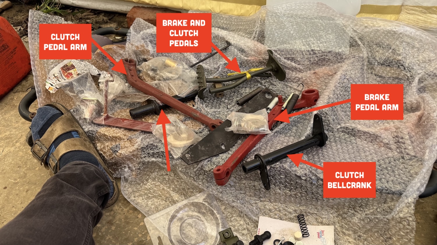
Some of these parts worked wonderfully, and some did not — not something that surprised me given the parts together cost under $200 (much cheaper than if one were to buy all the parts piecemeal).
Before I get into what went wrong, allow me to show, visually, how the pedals on this WWII Jeep function. There are two shafts/tubes under the Jeep — the pedal shaft and the clutch bellcrank. The pedal shaft passes through a tube-shaped hole in the frame while the clutch bellcrank slips onto ball studs — one on the transfer case and one on the frame.

The brake pedal arm slips over the pedal shaft and is prevented from sliding off via a washer and cotter pin, so pressing the brake does not rotate the pedal shaft, it simply pushes a plunger into the brake master cylinder, activating the brakes (see below). The clutch pedal, though, is keyed to the pedal shaft, so pressing the clutch pedal rotates the shaft, rotating the shaft’s ear, pulling a rod that is connected to another ear on the clutch bellcrank located about 10 inches behind:

That rod rotates the bellcrank, pulling the clutch cable, releasing the clutch. This bellcrank was an issue. It is supposed to sit on two ball studs — one on the transfer case and and one on the frame. Like this:
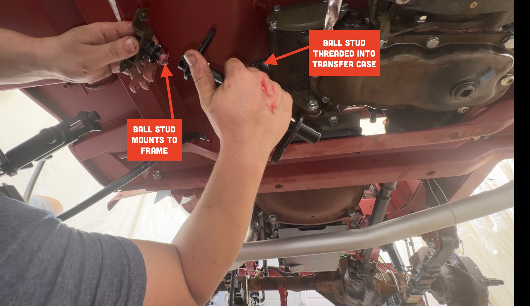
My first problem was that there wasn’t nearly enough space between the transfer case and frame; the clutch bellcrank simply would not fit. I checked the tube length and it seemed OK. Was the frame a bit off? Or was it the crossmember? How was I going to solve this? I already had the engine and transmission/transfer case mounted to the frame — I praying I wouldn’t have to yank that all off and somehow modify the frame? There wasn’t any time for that.
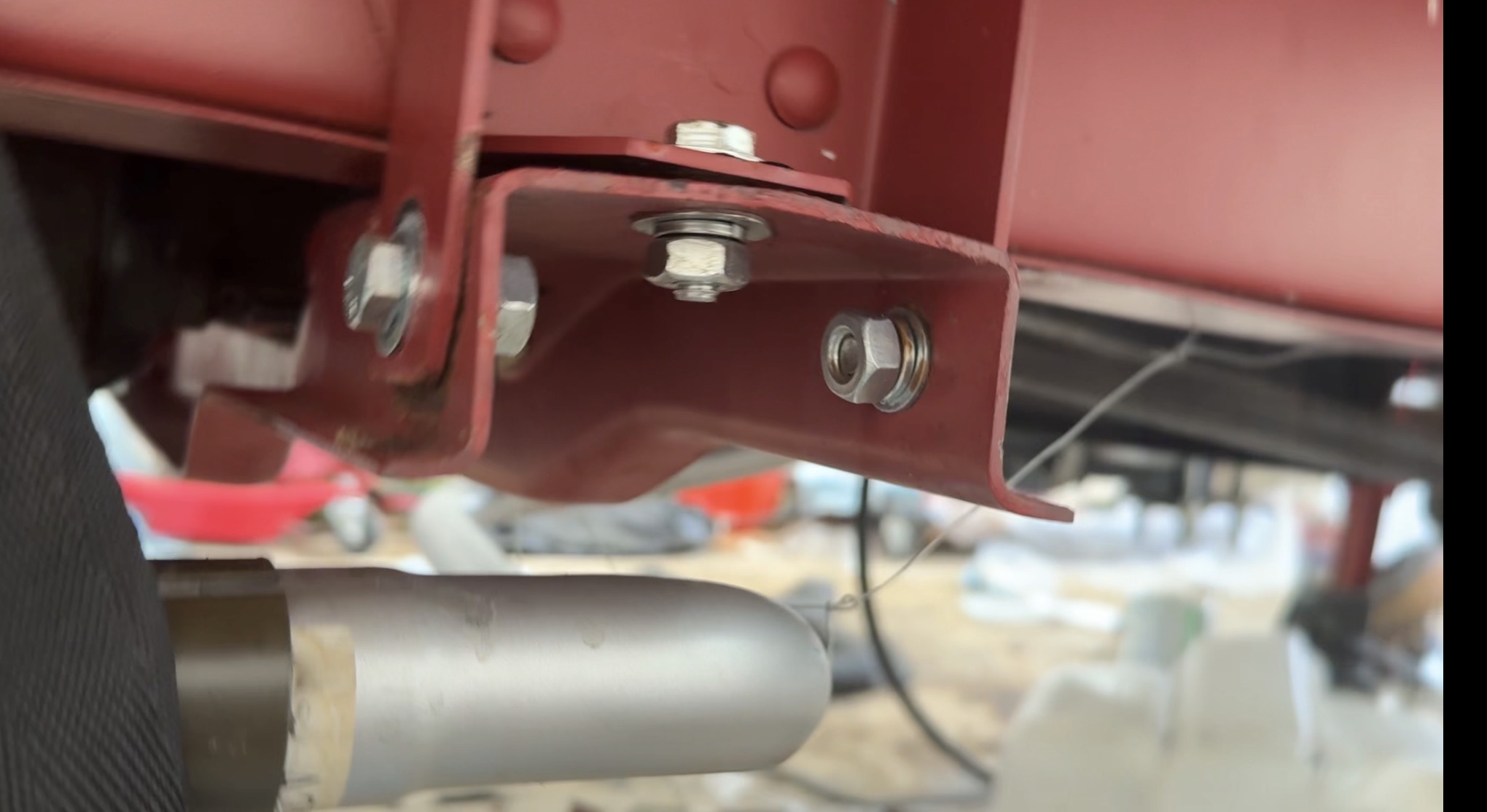
So I hatched a plan. I loosened all the bolts holding the transfer case crossmember to the frame. From there, I hooked up a ratchet strap to the transfer case and to the far side of the frame, with the idea being that cranking down on that ratchet would pull the transmission and crossmember towards the passenger’s side, yielding more room between the transfer case and driver’s side of the frame.
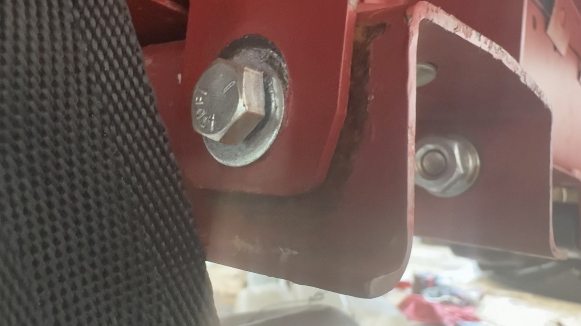
This actually worked! There was enough slop in those crossmember holes to shift the whole thing over substantially; this was a huge weight off my shoulders.
Now that I got the inexpensive clutch bellcrank fit, I found that it had the wrong inner diameter, meaning it would not slide over the ball studs. Luckily I had a ream that was exactly the right size, so I put the clutch rod in my vice, reamed it out, and installed it.
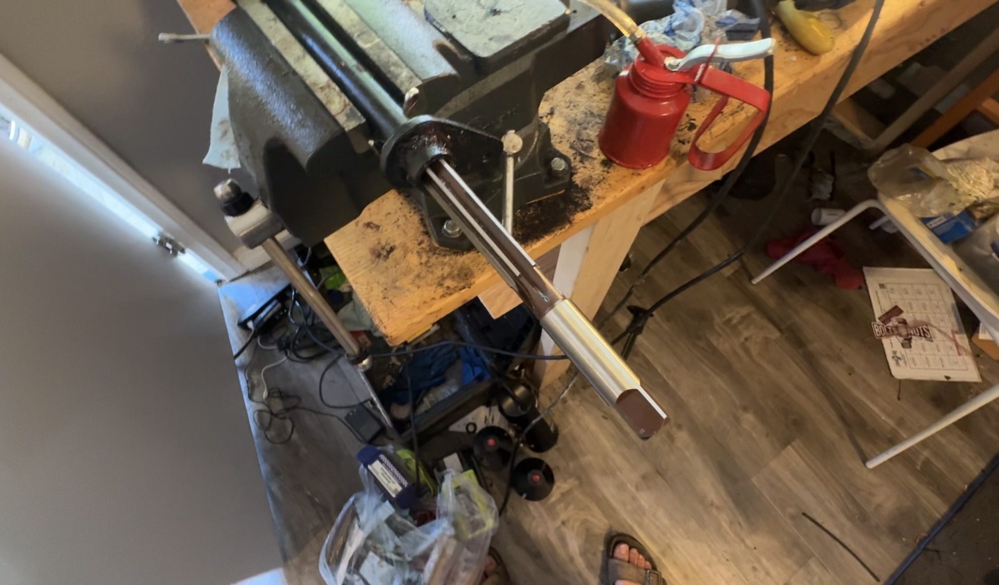
It worked!
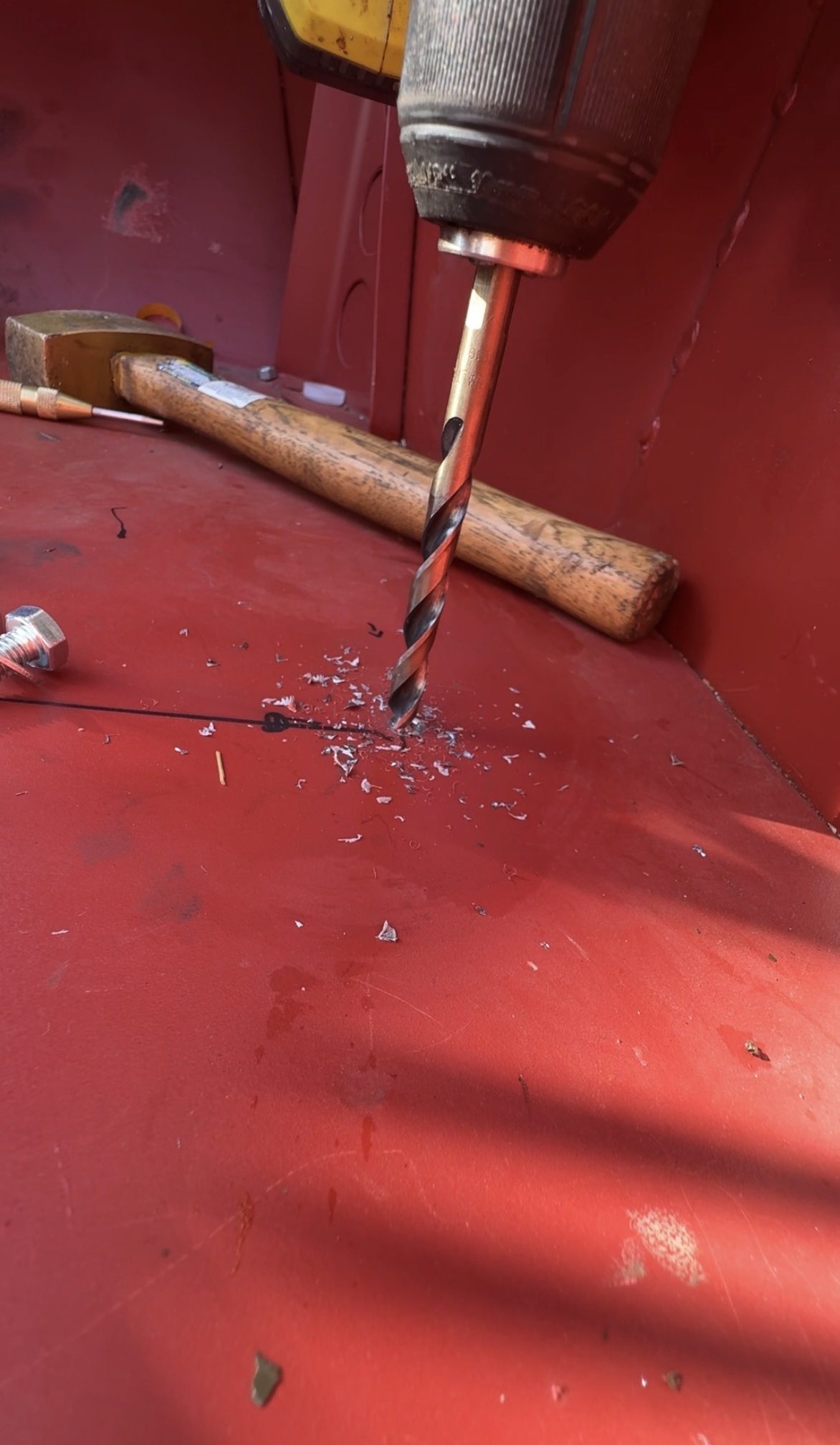
But then when I went to adjust the clutch cable, I noticed that the “ears” of this pivot tube weren’t clocked exactly right. They should be 180 degrees from one another, but they weren’t, and I was worried it could cause some kind of binding of the clutch cable.
I hopped on eBay and bought a better part.

This was a phase of the build in which the price of my parts was higher than at the beginning, when I could afford to take a risk on less expensive components. In my last month of this build, if I needed a new part, I was getting the best of the best — stuff I knew would fit perfectly, and with as few modifications as possible.
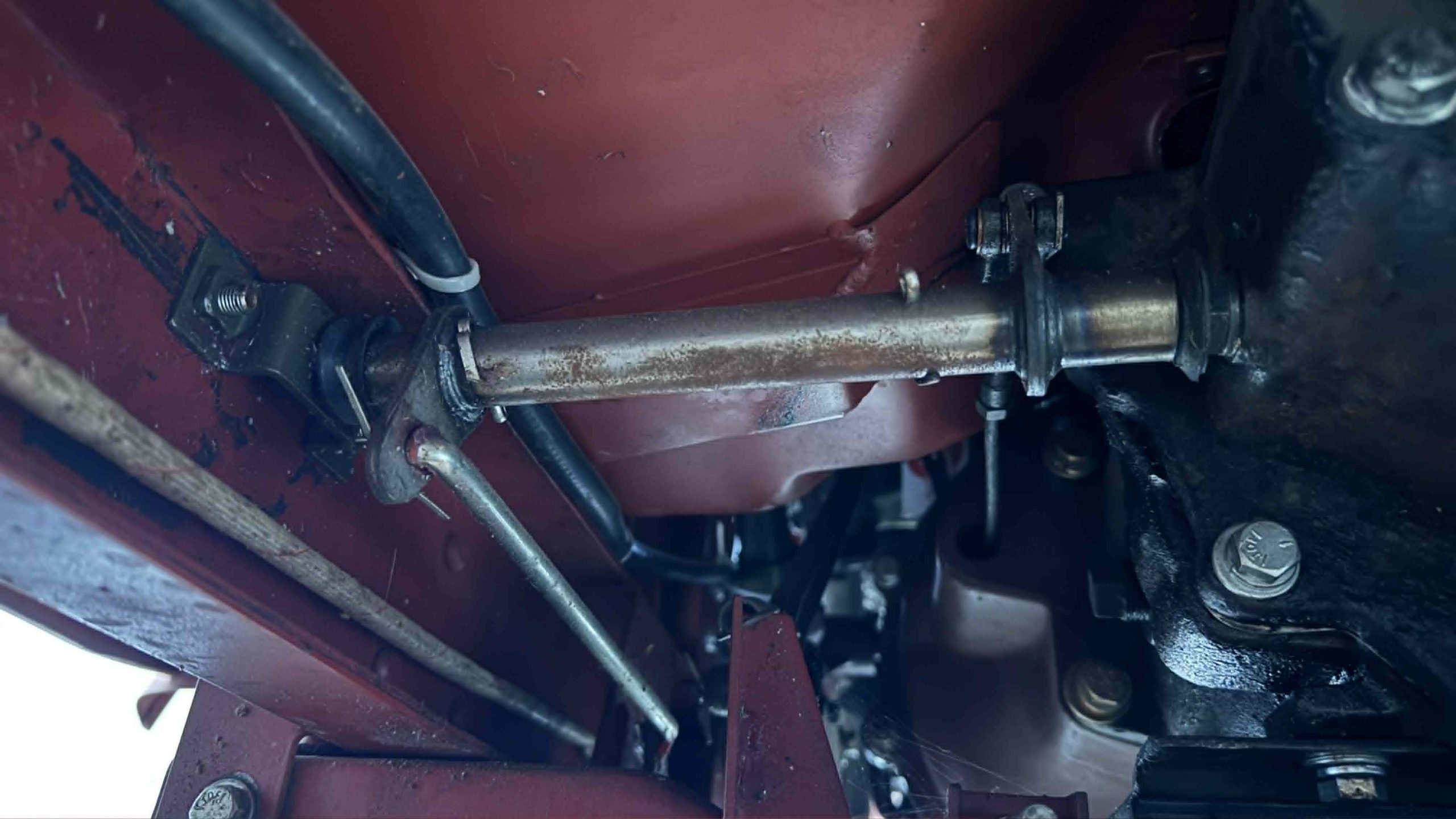
It may not look like much since I didn’t have a chance to paint it, but the bellcrank above rotates beautifully about those ball studs. I would later also purchase a new brake pedal tube (shown below) to replace the inexpensive one that had come in the kit.

At this point in the build, I had enough obstacles ahead, and I could not let my own cheapness be one of them.
Installing The Body Tub Was A Chess Match
I mention the pedal issue because it was actually the pedals that made it so hard to mount the body.
If you look at how a WWII Jeep’s body mounts, everything seems simple. There are 12 holes in the frame, and 12 holes in the body. You simply place a rubber mount between the frame and body, then shove a bolt through the hole, and boom — your body is mounted to your frame.

Looking at the images above, you can see that there are four mounts on the rear bumper, then two in the rear cargo area/rear footwell, then two on a flange near the center of the tub, two on a hat channel running roughly through the center of the fuel tank, and finally two on a north-south oriented hat channel.
These holes are constraints in the body mounting process, but there are others. See that big hole in the center of the body tub for the transmission and transfer case levers? That has to be placed just so such that those shift levers can experience their full range of motion without touching the body tub, plus that transmission top cover must remain removable:
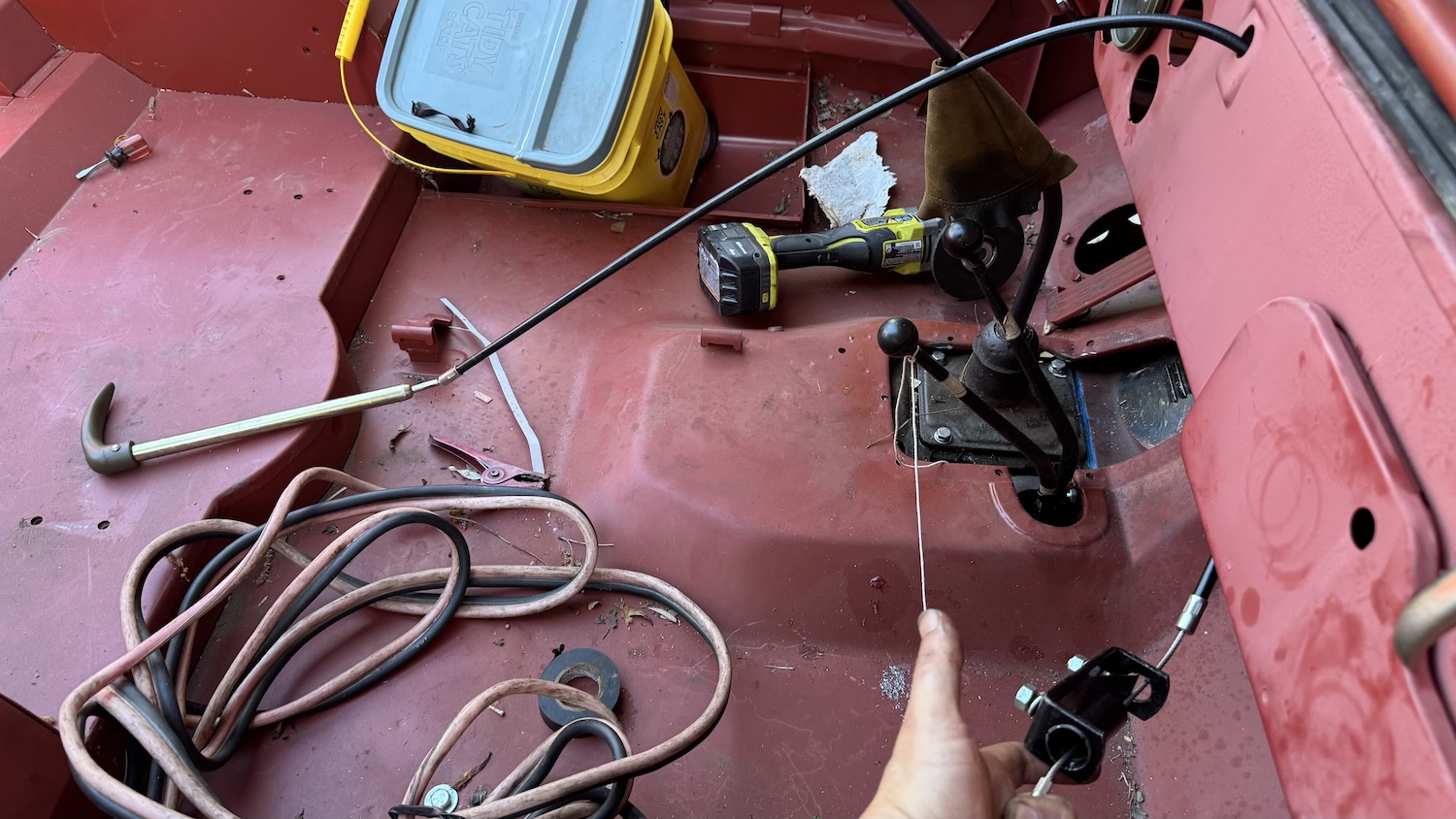
The other constraints are the grille mounts, which are on/near the front crossmember just aft of the front bumper, as well as the fender mounts, since those bolt up to the frame just aft of the front shock mounts:

Installing the body tub — which weighed probably 400 pounds — onto the frame wasn’t too challenging, and took three adults. Before Laurence had left, we had installed the body to test fit everything.

It was during that time that the body was mounted that I shifted it around and noticed a major issue: The holes did not line up.
It wasn’t just the body mount holes that were causing issues — in fact, I bet if it were just a matter of installing the tub onto a bare frame, those would align just fine. But the reality is that this wasn’t just dropping a body onto a bare frame — there was an engine and there were pedals.
The Engine Problem Was A Potentially Dangerous One
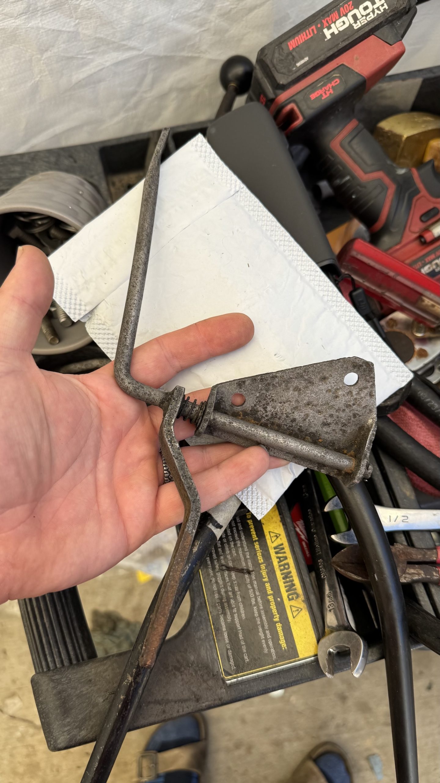
Let’s start with the problem of the accelerator pedal linkage. I had purchased a rather rusty one on eBay for $10 bucks, since these are not parts one can buy new.

I dipped the linkage into some Evap-o-Rust:
And then with a new spring, some new washers, a coat of paint, and some grease, that linkage was looking and functioning nicely:
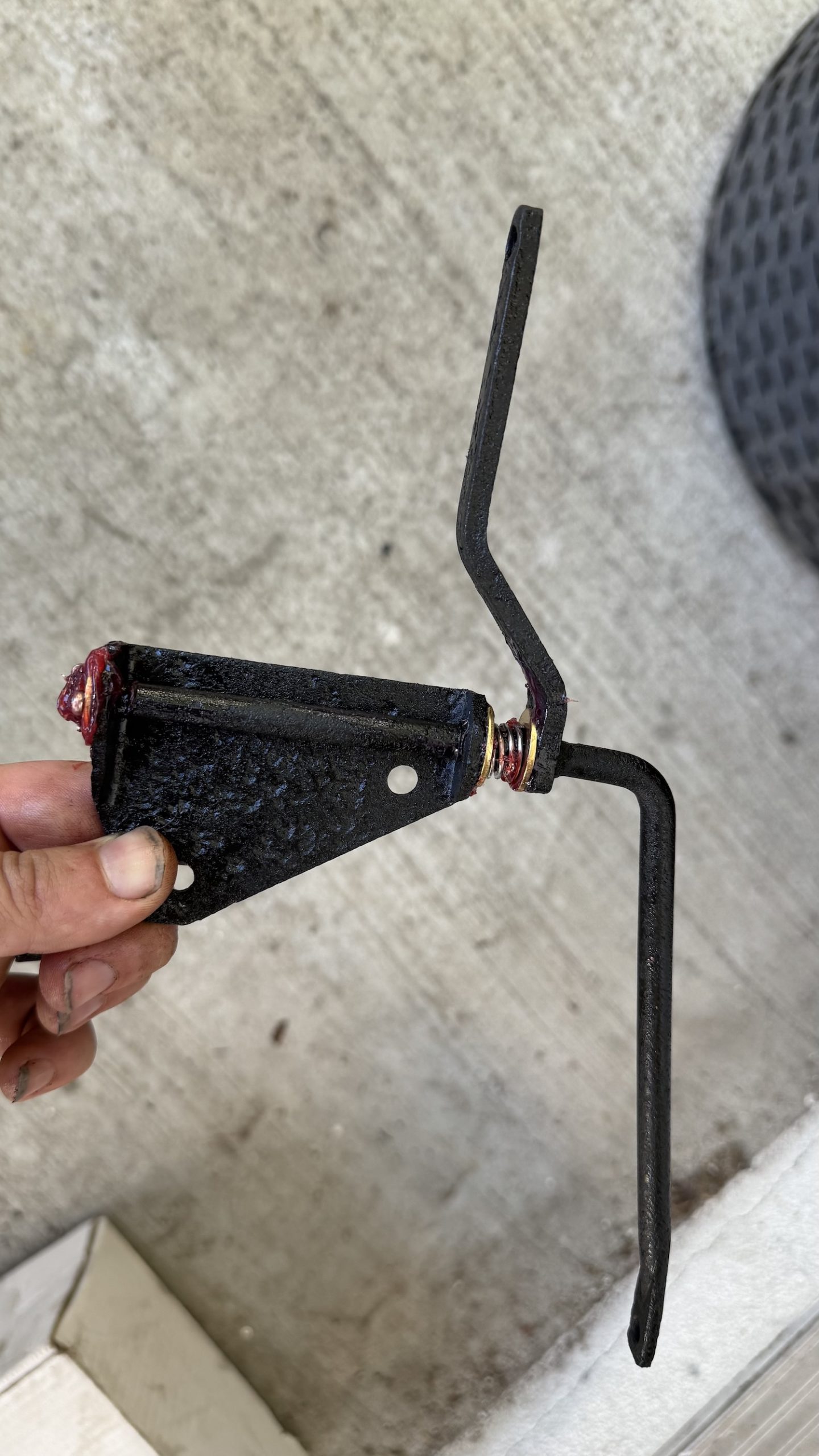
The issue with the linkage is that it sits on the rear of the engine block. If I were to shift the body tub such that all the frame/body holes aligned, and the pedals/steering holes matched up, I’d end up with a problem:

The body tub would hit the accelerator linkage, and in the worst way possible — it would actually open the throttle!
I had to make sure that there was enough gap between the body tub and the accelerator linkage such that any shift of the body on its mounts — or any shift of the engine — would still prevent the body from touching this linkage.

I had to avoid unintended acceleration at all costs, because off-road, there will be a lot of flexing of the body and frame, and on those rocks of Moab, Utah, I cannot afford to have the throttle opening without my say-so.
The Steering Column/Pedal Problem Was Hard To Solve
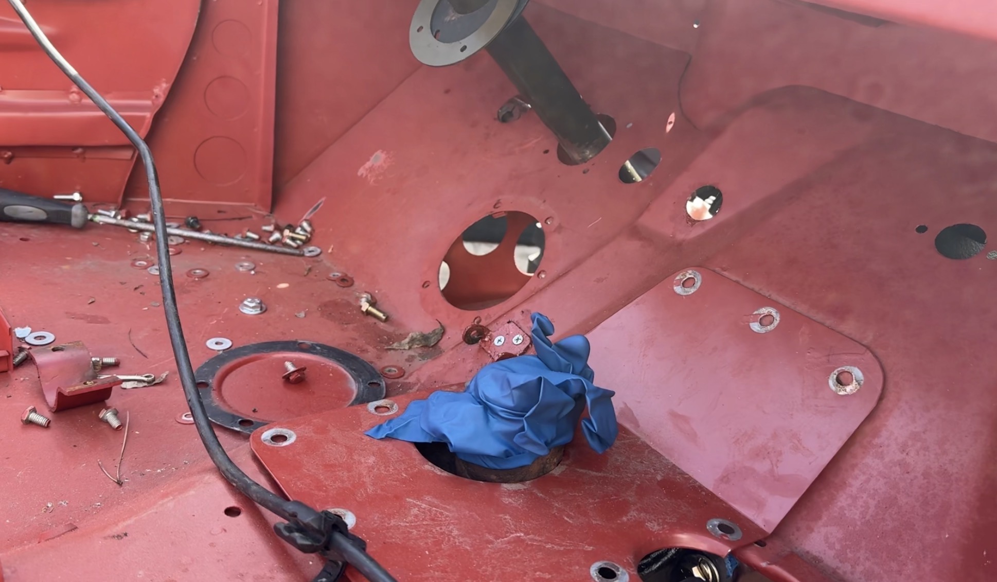
In the photo above, the hole to the left of the steering column hole is for the clutch pedal, and the hole to the right is for the brake pedal.
I found myself in a situation where, if I maneuvered the body in such a way that the frame/body mounts aligned, and there was sufficient space between the body and the accelerator linkage on the back of the engine, the pedals simply would not align with those holes.
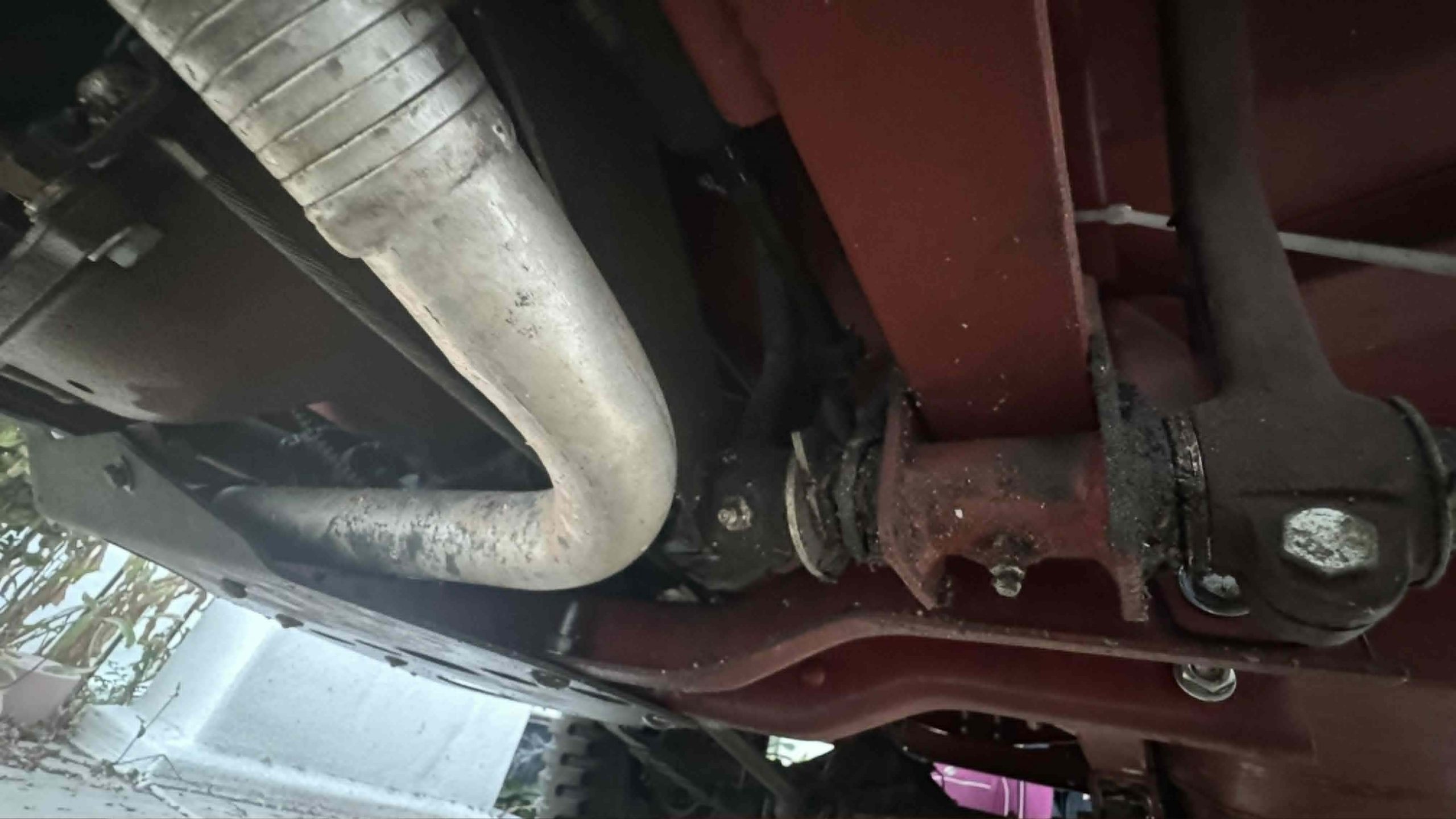
I had a few levers still to pull. Since the clutch and brake pedals both ride on a pedal shaft in the frame, I could add washers in such a way that would push the pedals outboard or pull them inboard. This helped a bit, and in fact, I was able to get the clutch pedal lined up nicely
But my brake pedal was nowhere close to the right spot; it was too far inboard relative to the hole. I asked my friend Brandon about this, and he told me that the brake pedal on a WWII Jeep is actually not perfectly straight:
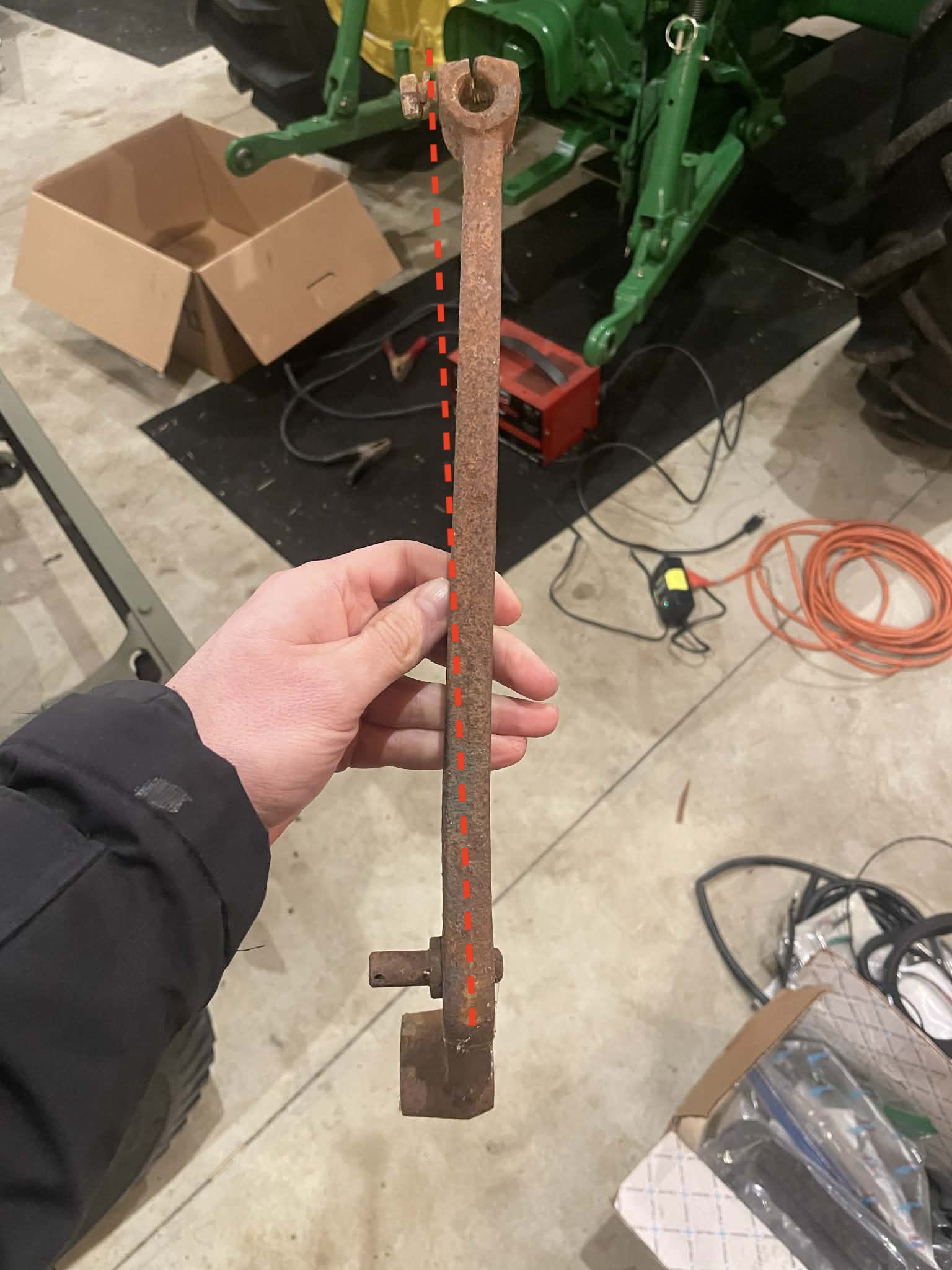
Interesting!
The bend seemed quite subtle, but it was already the first week of March and I was supposed to leave on the road trip on the 28th, so I quickly put a bid on an original WWII Jeep brake pedal, and luckily won:

The bend looks more pronounced in the listing, and upon receipt, I found that the body hole lined up nicely with the pedal! Only, there was a new problem. My brake pedal was now hitting my steering column:

To combat this and to get the optimal spacing of the pedals so they’re centered in the body holes, I bought the new pedal shaft I showed earlier. This helped with alignment and slop in the brake pedal, but it was still hitting the steering column.
I sanded down the little slots in the brake pedal so that, when I installed the cross-bolt, the pedal was perfectly straight and not crooked:

But the pedal still hit the column.

In a last-ditch effort to try to fix that brake pedal slop, I called one of the most iconic automotive shops in America, Blair’s Speed Shop in Pasadena. An older gentleman on the phone directed me to a place called Valley Brake & Wheel in El Monte, just east of LA. It was there that I met a veteran wrench named Richard.
I had brought in a brass bushing I had found at Ace Hardware. It was the right inner diameter, but the length of the bushing was a bit short for my pedal, so I bought two. Maybe Richard could press in both.
“One sec,” the older gentleman said. In about three minutes he came back with the perfect brass bushing. “I’ll have this done for you Monday,” he promised.

Indeed, Monday came around, and Richard had bored out my original brake pedal and pressed in a brass bushing, all for $40.

I installed the pedal arm onto the new pedal shaft, and it fit tight, no longer touching my steering column. Amazing!
The Competing Constraints Means The Body Isn’t Perfect

Once I knew where I wanted the body to sit, I put the tub on some sawhorses (see above), and I began drilling the body and frame prior to reinstalling the tub.
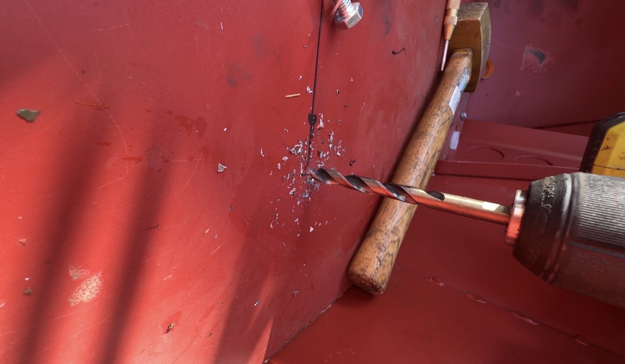
It was during this phase that it became clear things weren’t going to be perfect.
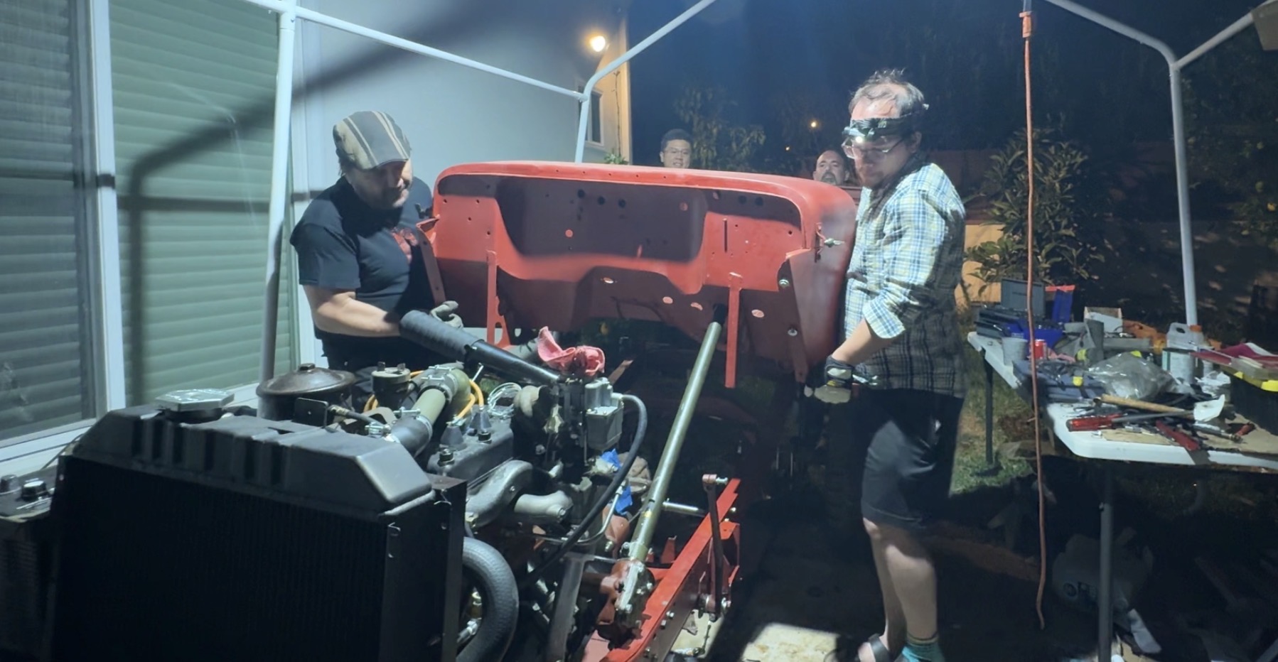
Getting the steering column and the pedals to fit in the holes, ensuring the body was far enough rearward that it wasn’t hitting the accelerator pedal linkage, getting the transmission/transfer case shifters to fit, and then finding a way to bolt up all 12 body mounts was a huge challenge.
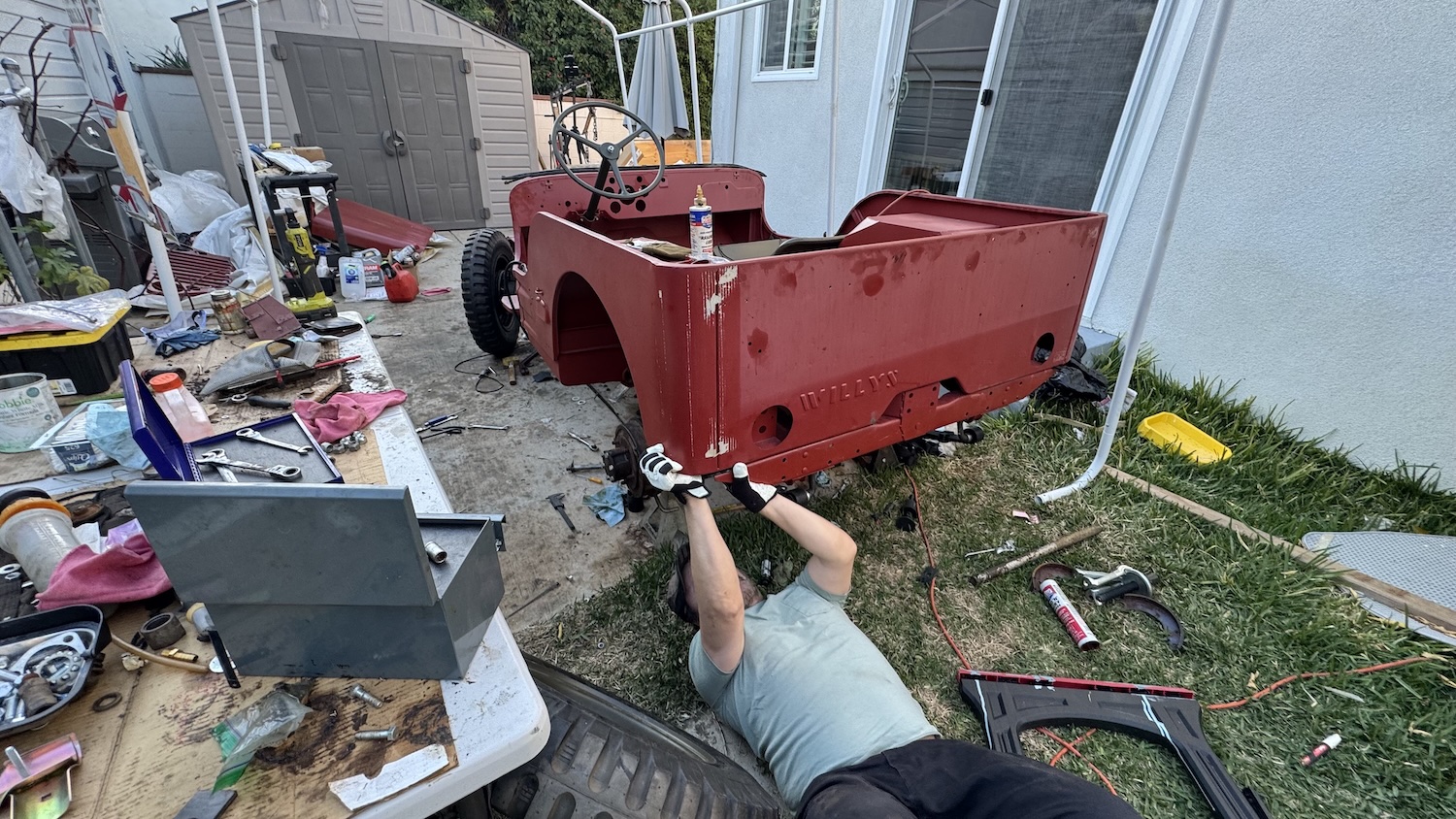
The reality is that I had to make a compromise somewhere, and the area I chose to prioritize was the pedals. If my accelerator pedal linkage were to be pushed by the body, that would be a safety concern. If my clutch and brake pedal were rubbing against the body, that could compromise the vehicle’s function. So I focused on lining up the pedal holes and keeping the body far enough rearward that it wouldn’t hit the accelerator pedal linkage. The result of this prioritization is that the rear of the tub hung isn’t perfectly flush with the rear bumper — it hangs off a tiny bit:

In addition, it’s clear that the body might have a slight yaw to it. Check out the front grille; it’s mounted perfectly perpendicular to the frame:
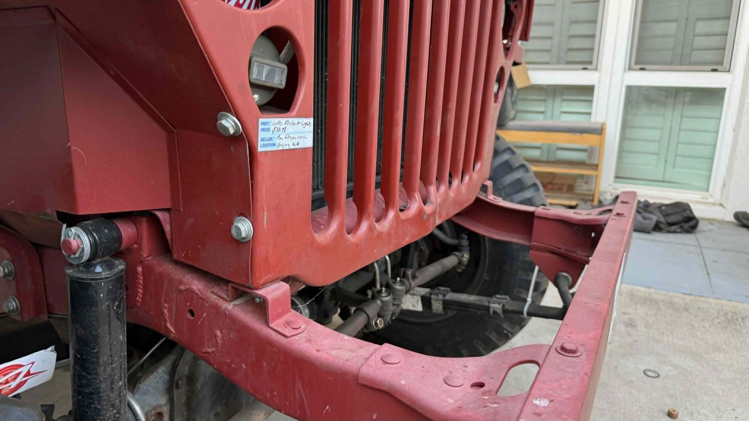
However, the hood overlap is more on the passenger’s side than the driver’s side. Here’s the driver’s side hood overhang:

And here’s the passenger’s side:

What’s more, the body mounts on the driver’s side line up reasonably well. The front one fits perfectly:
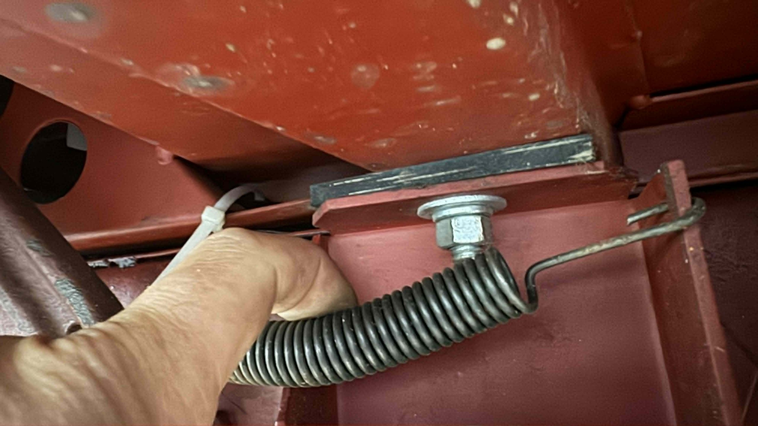
The second two mounts on the driver’s side required a bit of oval-ing out of the frame mounts, but it wasn’t too bad:
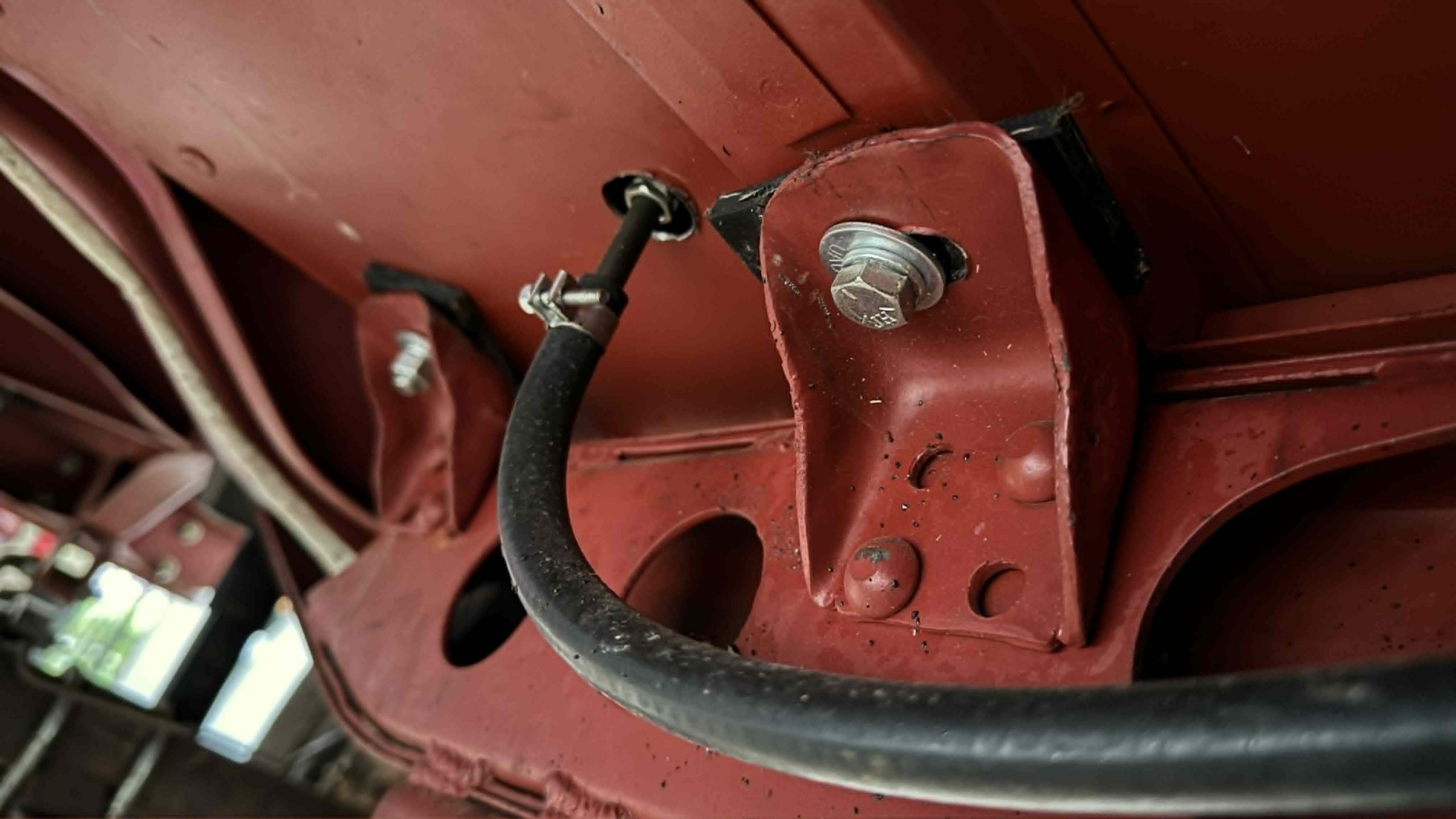
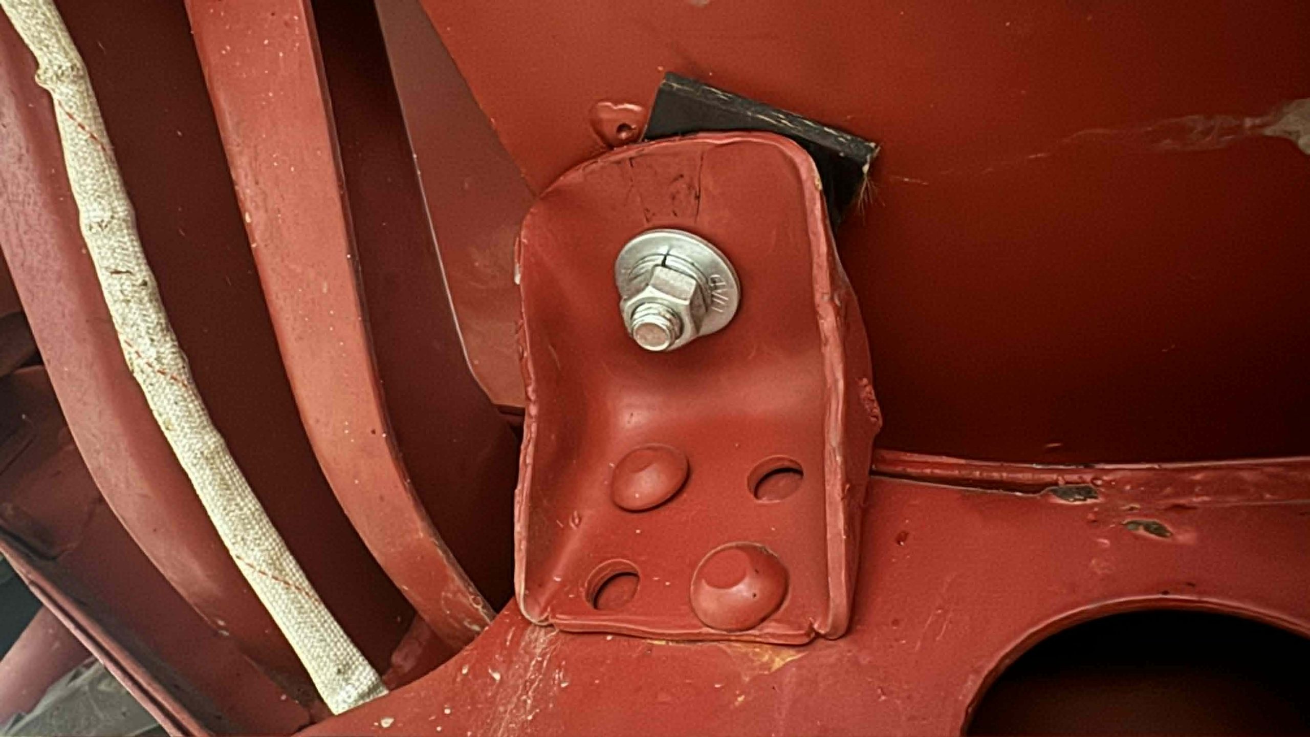
Here you can see that the third mount does indeed go into the flange on the body. It’s a little close to that front vertical face, but it works:
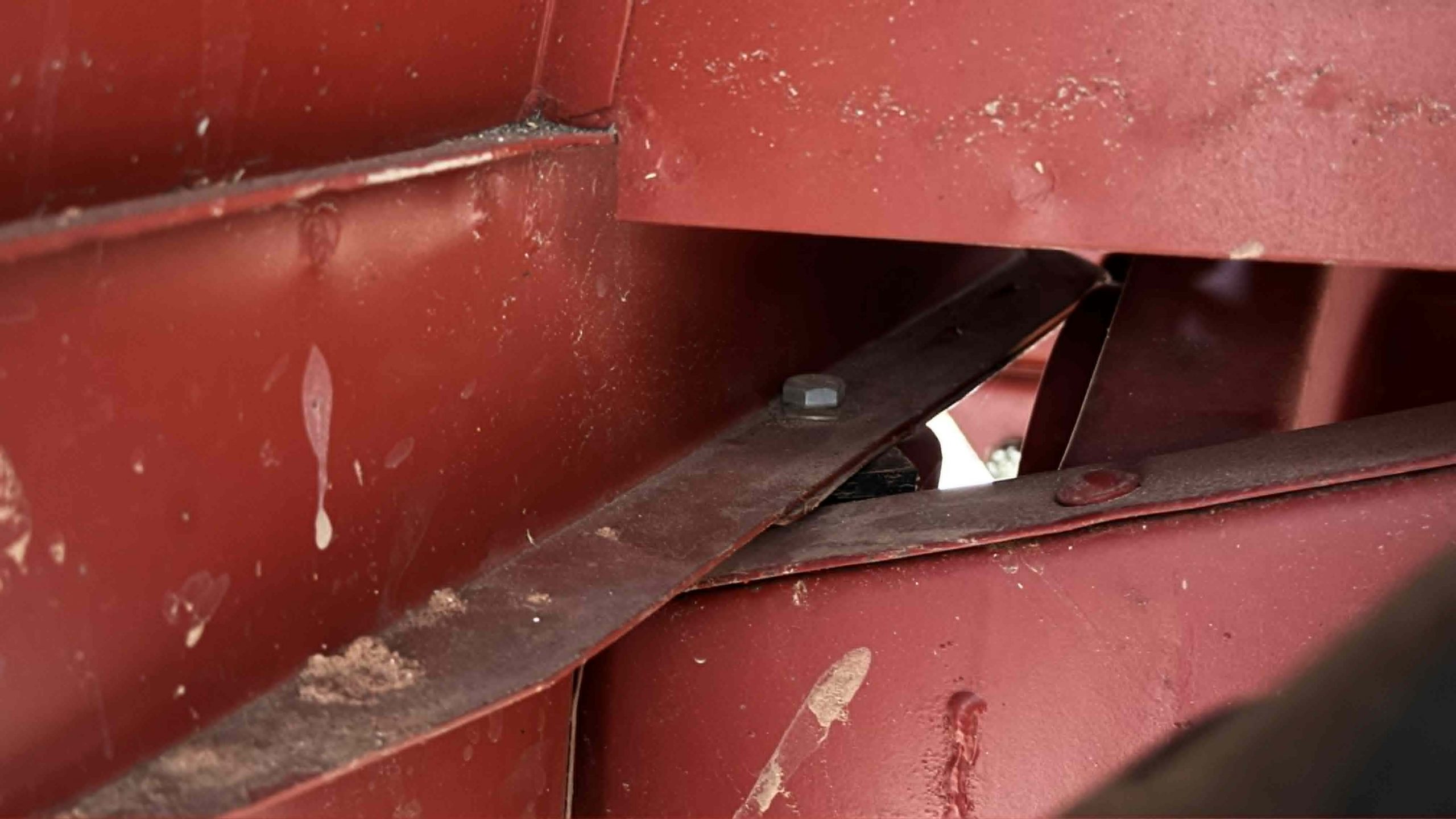
Meanwhile, on the passenger’s side, I had to drill a new hole in the frame mount, about a half inch aft of the existing one:

The second mount was lined up well enough with the hat channel that it worked out, but you can see that the third mount required me to drill a hole aft of the existing one.

The existing hole was lined up with the vertical part of the body in the image below; in order to give the new frame hole enough space from the existing one, I had to drill the flange fairly far rearward:

In the photo below you can see the rearmost body mounts — both the ones on the bumper and the ones in the cargo area:
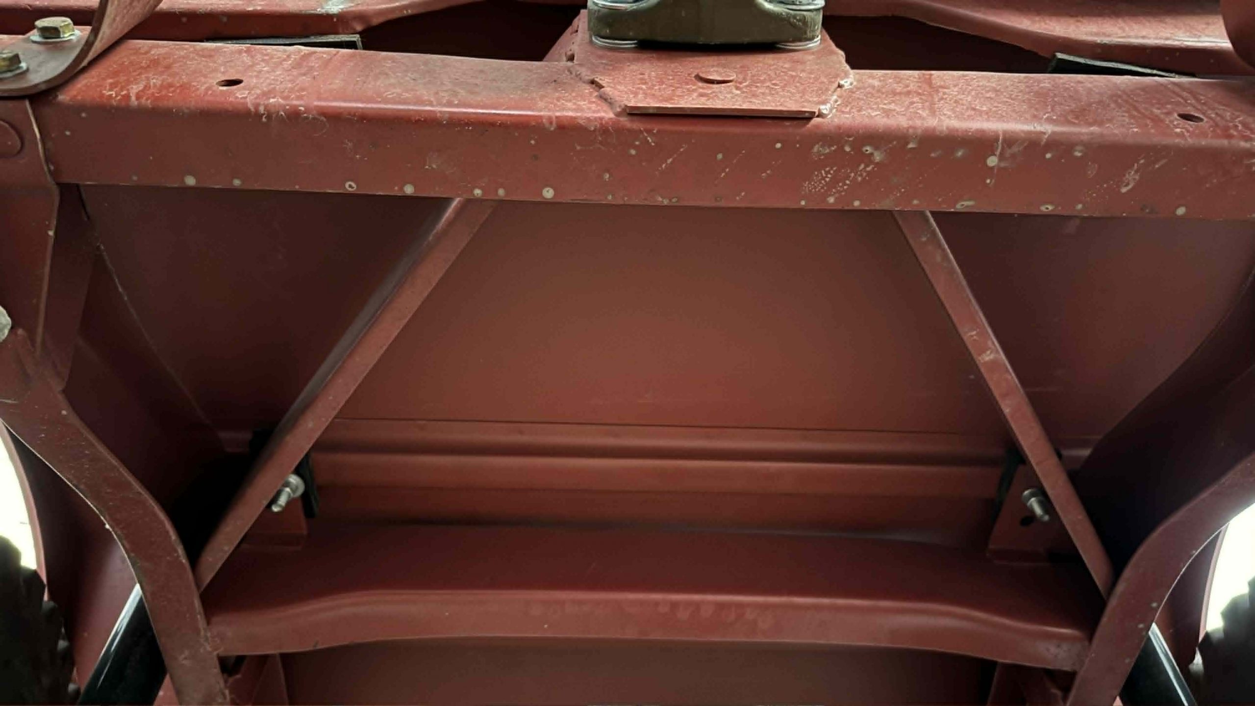
In order to get the bolts through the hat channel/stiffener in the cargo area, I had no choice but to drill new holes in the frame: 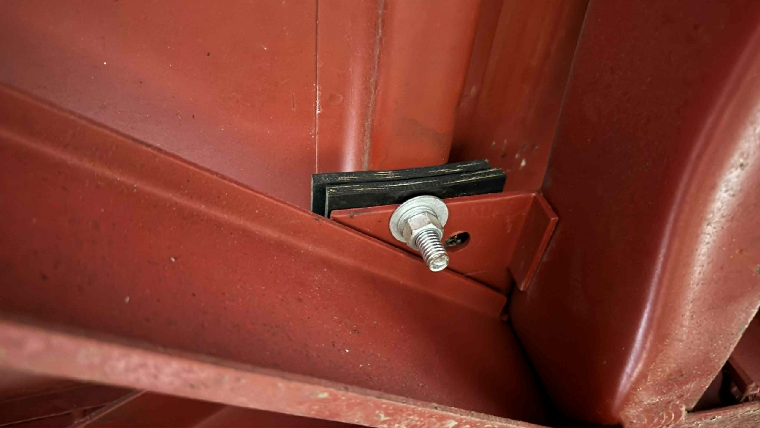
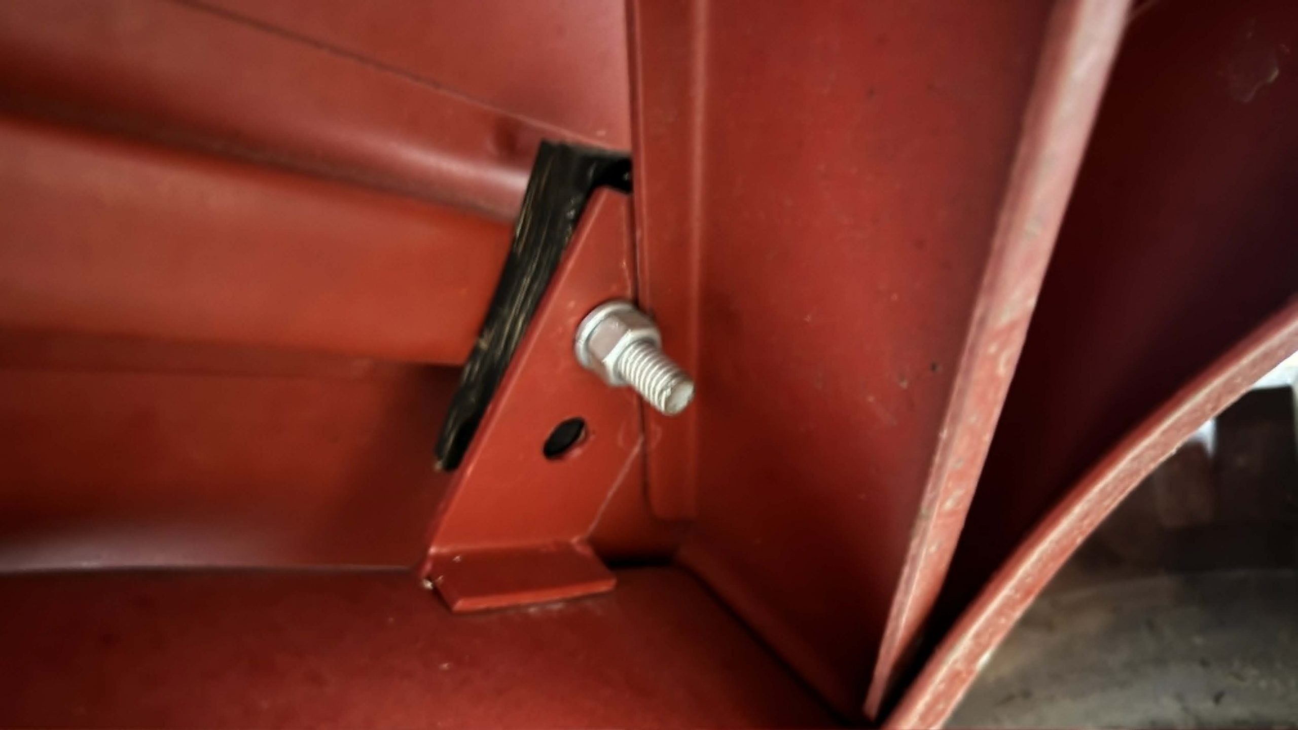
The body mounts for the rear bumper were really no issue; the L-brackets on the back of the body were bendy enough that getting the holes to align with the rear bumper/frame wasn’t an issue:
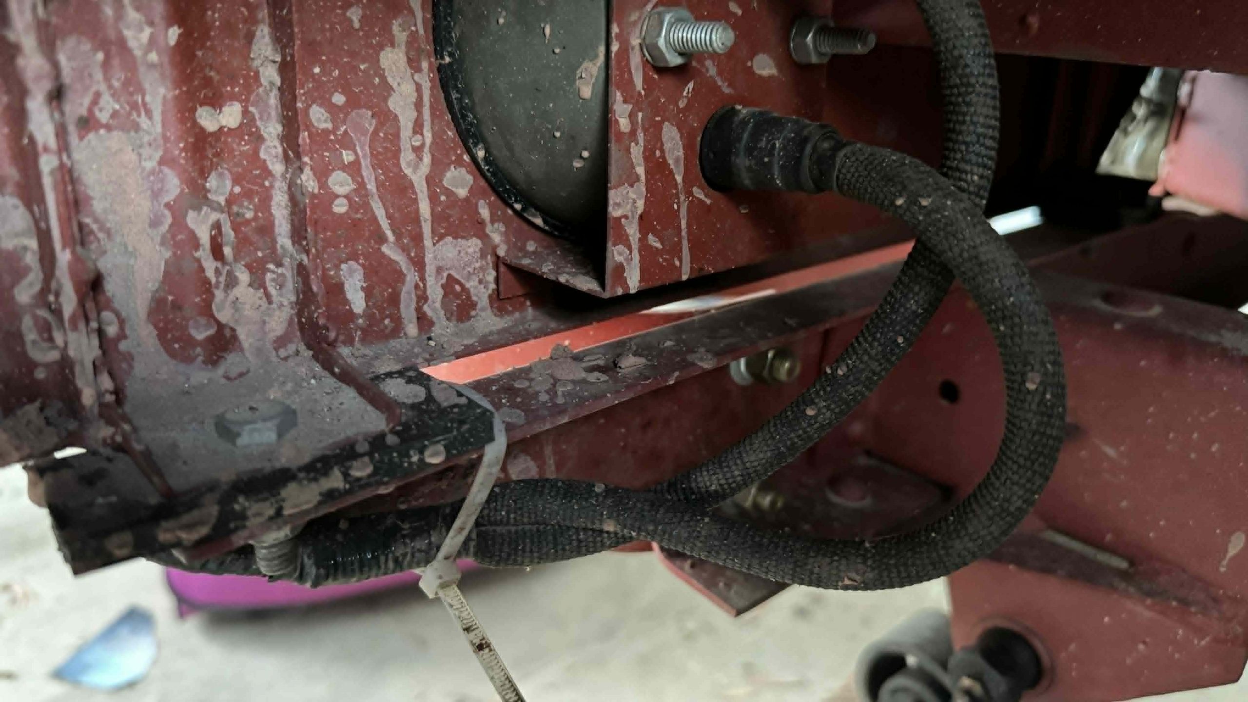
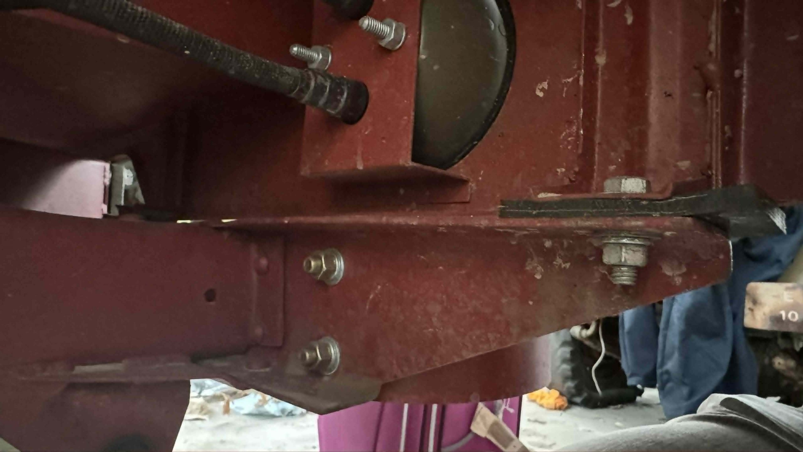
Once I had everything lined up and the bolts loosely in place, I did the final tightening:
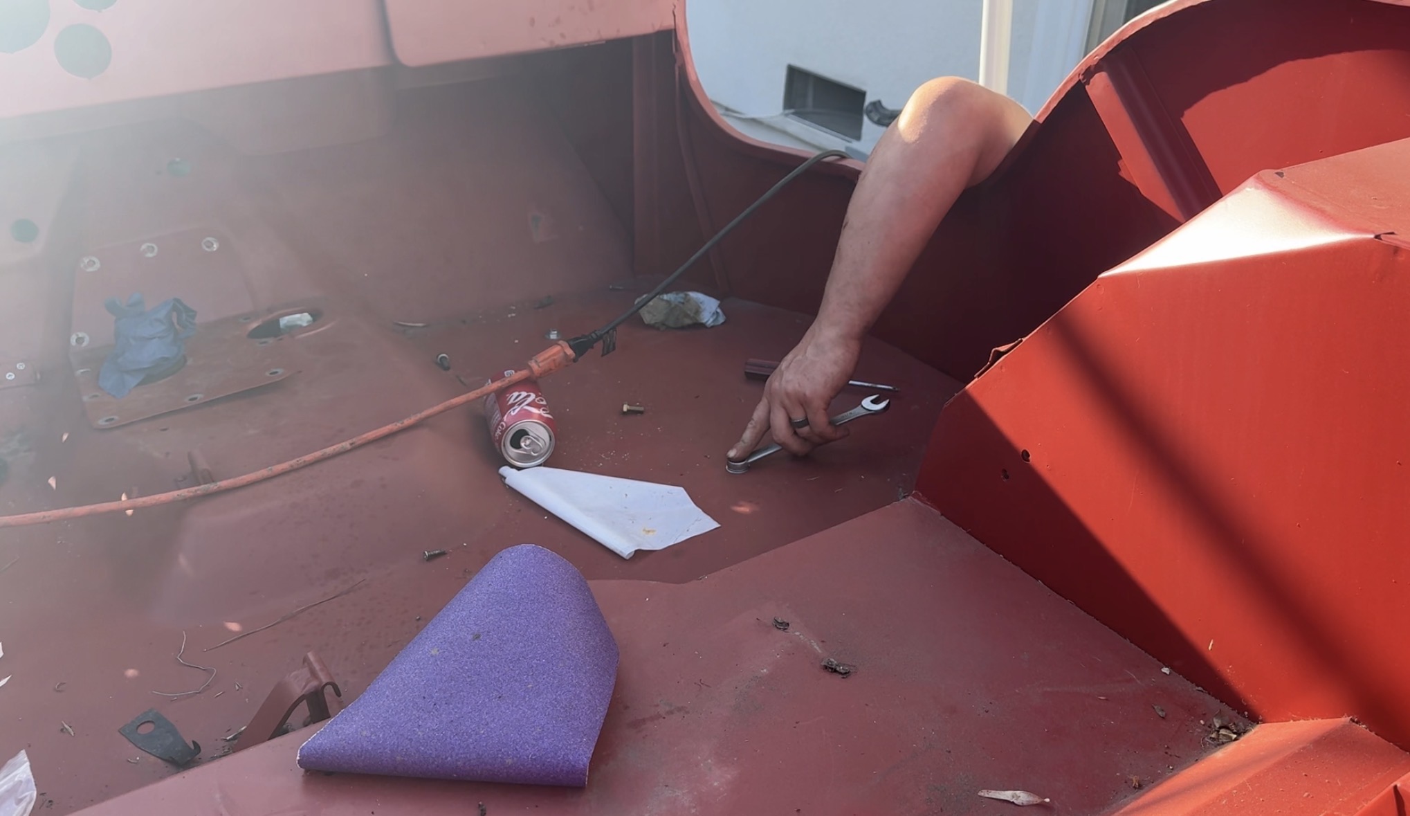
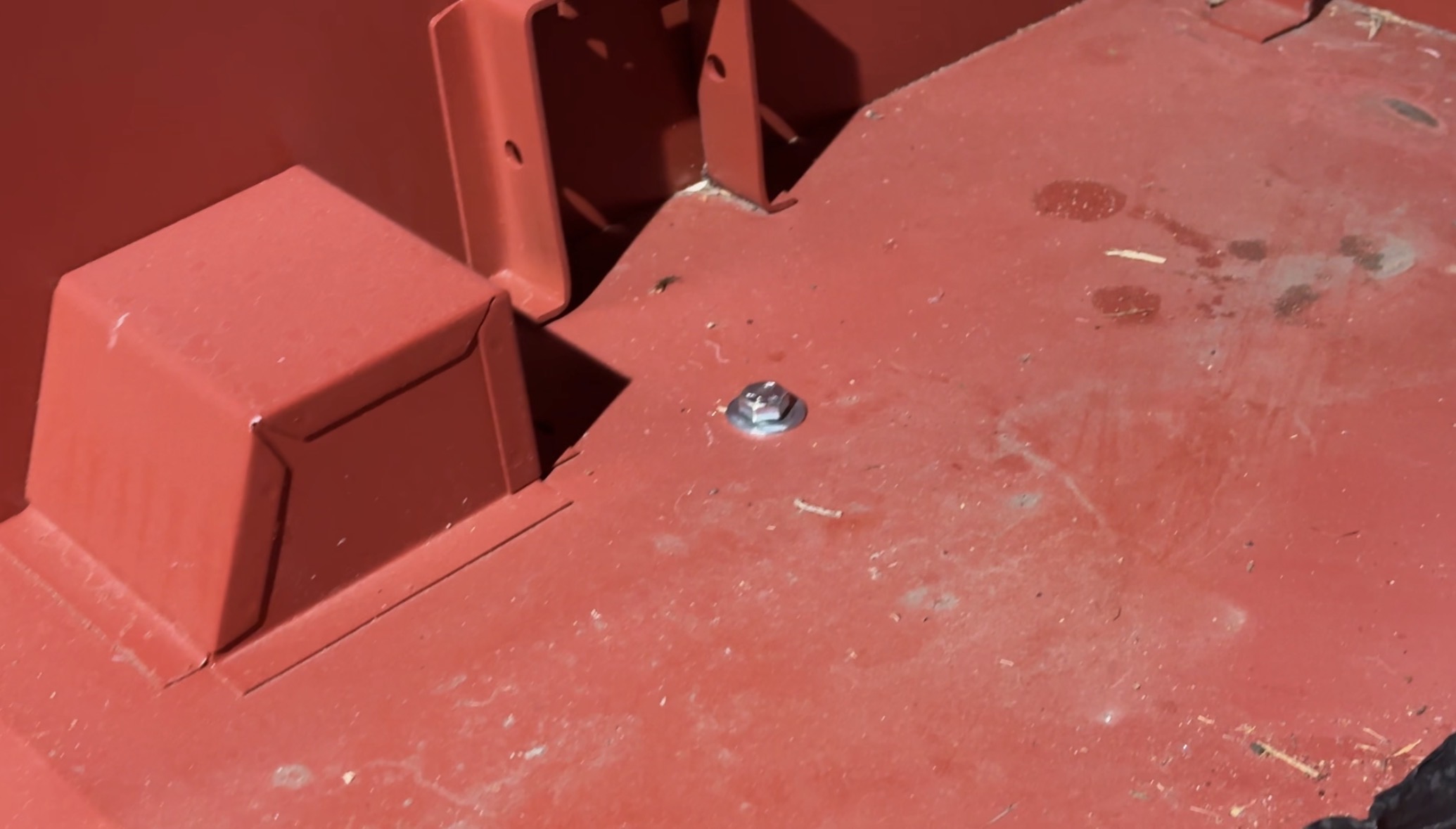
I then immediately loosened those bolts again when I found that I couldn’t install the fenders.

The Fenders were tricky because they mount to the tub, the grille, and the frame, all of which are fixed, but none of which are really precisely located. I bolted up the grille first, since I wanted it to be straight/perpendicular to the frame. The body was where it was going to be since I had drilled all the holes considering all the other constraints. I had not at all considered the fenders prior to drilling these holes, and this made things tough. Exacerbating the issue was a frame with holes far out out of alignment:


The solution involved installing the front fender bolts loosely, greasing up the fender and bashing it with a ball-peen hammer until the top rear corner slipped in front of the body tub.
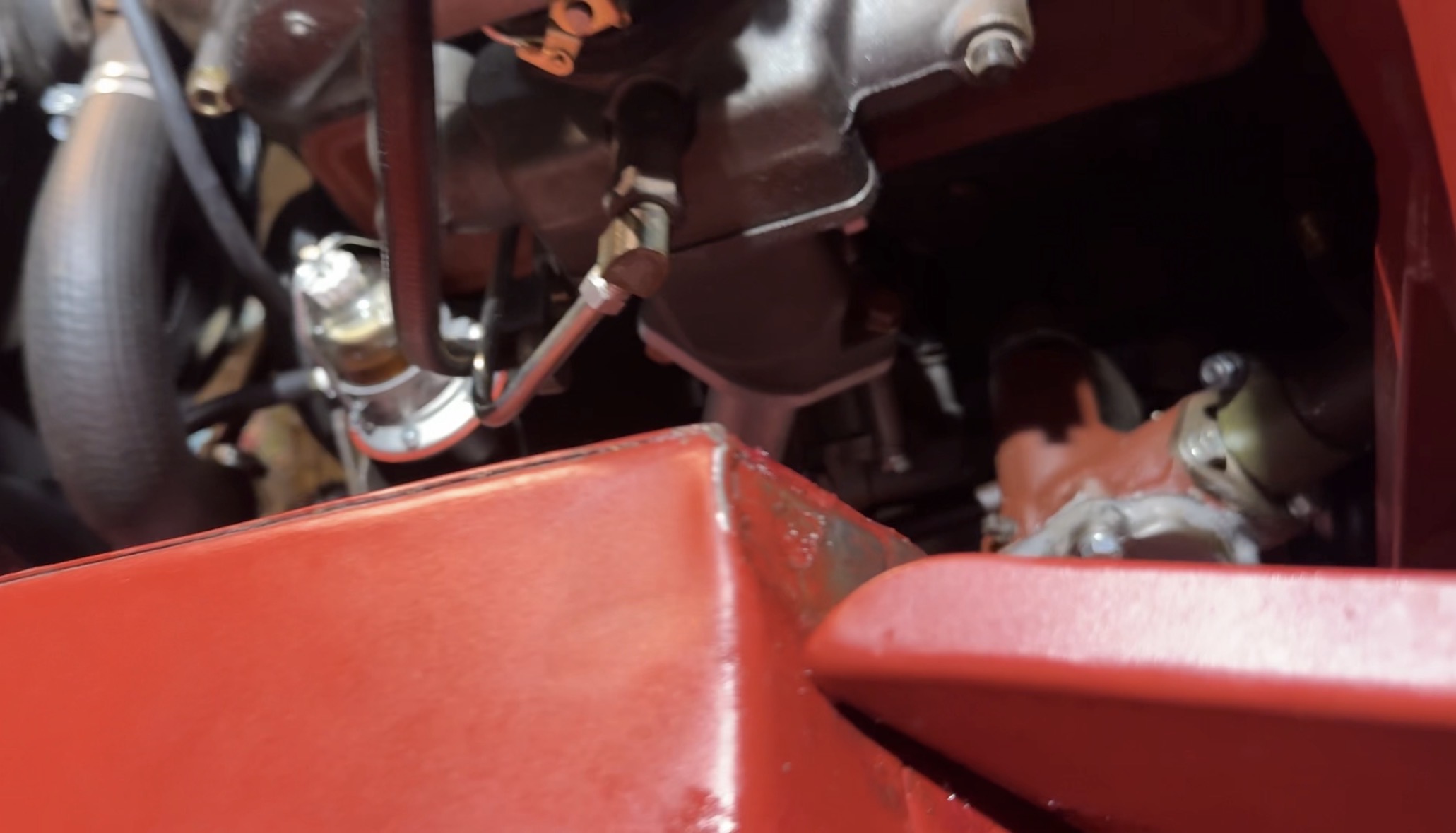
The bottom rear part of the fender was not even close to aligned with the tub, but I just used some longer bolts and gradually pulled the fender flush.
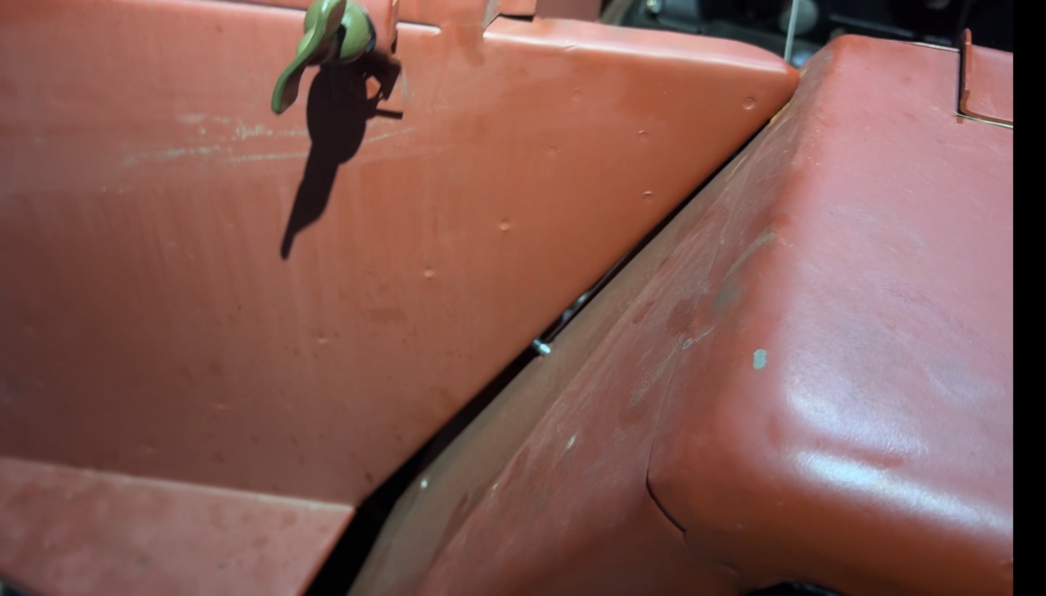
I thought these compromises would bother me. There’s a bit of an overhang in the rear, the hood overhangs the grille unevenly, the body mounts in the frame required new holes next to existing ones, and I had to ding the inside of the fender a bit to get it to fit.
But the fender ding is hidden under the hood, the rear overhang is barely noticeable, and the front hood overhang also doesn’t seem like a big deal. There’s something about the WWII Jeep’s design that almost seems to hide imperfections. The Jeep looks amazing, and as I work to install things like headlights, seats, the rear spare tire, a windshield, and a steering wheel, it will just look even better.
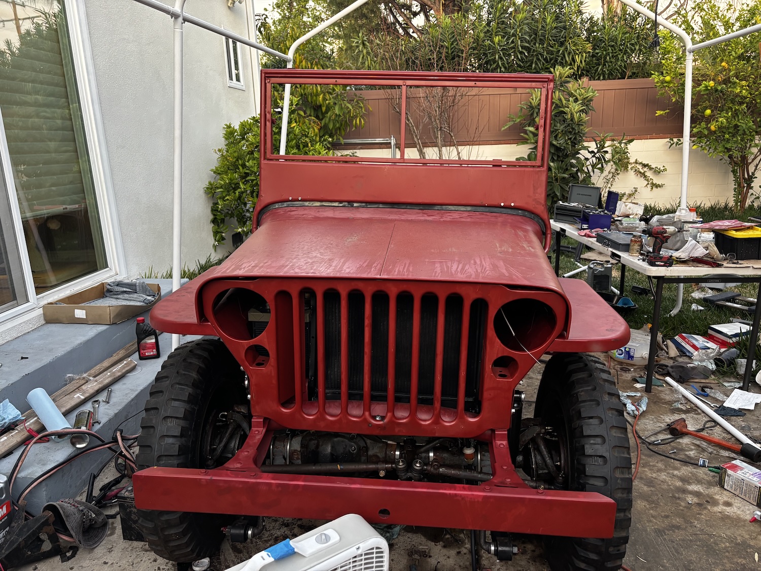
What an ordeal it was getting the body mounted onto that frame. But with that complete, my focus shifted towards finally trying to take the Jeep on its first test drive. If I had a major issue with the powertrain, I needed to know now.


Sounds like the new ebay Willys shares alot more in common with an original than you may have guessed. I have a largely original ’44 MB and nothing lines up. I removed the front fenders to install welting strips and repaint. When I reinstalled them, nothing lined up right. The grille is not quite perpendicular, the hood overhang is uneven and it all required quite a bit of muscle and swearing to get all the holes lined up close enough for the bolts to fit. After 82 years just about everything has been tweaked enough to make it unique.
You know what. This eBay tie -in is working.
I hadn’t bought car parts from eBay in 5 or 6 years. And since this series started to pick up recently, I’ve bought 7 or 8 things for two different vehicles from eBay.
Not sure if I approve of that. But as a marketing thing it definitely worked on me.
Welcome to the world of aftermarket parts, everyone who has done restorations know that you need to prefit everything well before final assembly as there is ALWAYs variations in the parts. It’s very rare that something just bolts on like an original part even mixing parts from the same manufacturer.
You gonna paint it, or just let the primer keep absorbing moisture so you can get that sweet, sweet rust you crave?
I used to own a Jeep TJ, that turned out to be far rustier than originally expected. The floors were so rusty that I was considering a tub swap. I’m glad I came to my senses and sold it instead. I applaud your fortitude!
I felt your pain on that body alignment. I installed a fiberglass tub and fenders on my 73 CJ-5 a long time ago, only reusing the steel hood and grill. The tub came with no holes drilled in it anywhere, which was good and bad.
I had the old firewall as a template but the fiberglass tub had thickness to it where the steel one didn’t. Getting the steering column and pedal linkages to line up was a nightmare. Cut the holes, try the fit, hog out the holes, try again… Where the holes got embarrassingly big I used thick pieces of rubber to dress things up. In the end it worked out ok but there was a lot of swearing on that project…
I have a strong suspicion that “minor misalignment” may have been authentic on original models.
Fantastic article! You have an amazing amount of patience, persistence, talent and tolerance for frustration.
Great job documenting the whole process, too! This is a hell of a lot of work, rebuilding an entire vehicle.
And I feel a sense of accomplishment doing a successful brake job.
Your sense of accomplishment must be hundreds of times greater.
Great work DT! This whole saga was so awesome just like Project Cactus. Now this Jeep just needs more rust.
Since you mentioned being cheap, did Ebay have a set ballpark budget for this and they just wanted you to do what you could to keep it somewhat reasonable? Thank you
The goal was to just get it done. We knew it’d be pricey, since buying hundreds of parts one-by-one isn’t the most efficient way to assemble a car, but this was about discovering the art of the possible and executing.
Oh yeah, for sure…what an awesome project! Just curious, are you still gonna wrench your “cat” overlanding XJ?
ZJ!
I want to!
Oh yeah, duh! I knew it was the ZJ, I can’t believe I put XJ. Yup, I know you’ve had a lot on your plate. Thank you for everything you do. The Autopian is so awesome!
You know what makes getting metal with holes in it to line up enough to bolt together?
Get a bunch of tapered metal punches like these for example,
https://www.homedepot.com/p/TEKTON-3-32-in-Solid-Punch-66072/205820460
Then stick them in the holes to align them, and if they don’t align, start hitting things with a hammer until they do.
Oh, and a variation is to get extra-long bolts, grind them to a point, get the point in enough to wiggle and bash the bolt in, put the nut on, and grind the excess off.
Of course, when all this stuff came from the same factory, the jigs all matched.
A few thoughts:
Not exactly sure why you used a ballpeen hammer for finessing your fender – I would expect a dead blow hammer to impart less damage.
Fitting sheet metal parts is a pain – especially flat sheets that seem to move around way more than you would expect – I have spent way too much time trying to get machine panels back on machines after taking them off when everything looked just fine before disassembly. Bends and forms do tend to help panels keep their shape better – which is why “floorboards” are rarely flat and your hood is likely an assembly of multiple parts.
While I have never done this type of project, I am surprised the body panels came with all the holes pre-cut. I thought usually you had to drill at least some of them yourself to help you make everything fit. Maybe this is more of an industrial technique?
I have that orange deadblow hammer that everyone else has. That would not have done anything, because if you look at the part of the fender I’m trying to massage, it’s a sharp corner — high stiffness. I needed something that could really bend some metal out of the way. The POINT was to do damage; I needed that corner flattened.
The body panels did not come with all the holes. I had to drill the floor holes.
I have been thinking about this and others have spoken to it in regards to Repops. I don’t care if everything you bought was new, I would not expect them to fit without fabrication or modification unless they all came from the same factory or the parts were precision copies.
When restoring my car (64 VW Type 3), I had to utilize original parts from other year Type 3. My experience was only 80-90% fit first time. Each other year had slight variance from my year.
Can’t wait for the next story drop.